


A-8 Connector Pin Assignments
VGA Interface Connector
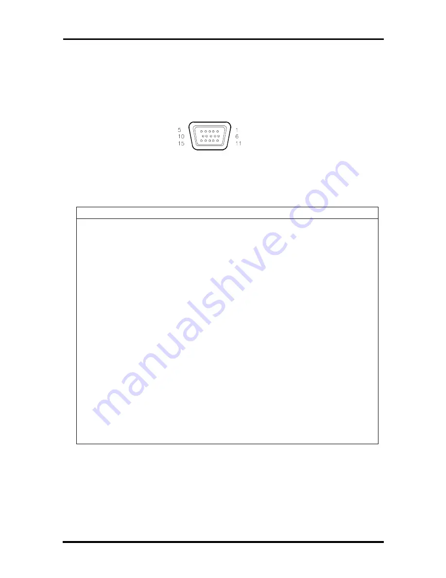
Video signals are output from the AGP or PCI video board through a VGA interface
connector, a 15-pin, D-subconnector (VESA VS890803-2) located at the rear of the system
unit. Figure A-10 and Table A-8 show the connector pin locations and pin assignments.
Figure A-10 VGA Interface Connector
Table A-8 VGA Interface Connector Pin Assignments
Pin
Signal
1
Red
2
Green
3
Blue
4
Not used
5
Ground
6
Red return (ground)
7
Green return (ground)
8
Blue return (ground)
9
+5V pull-up
10
Logic ground
11
Not used
12
DDC DAT
13
Horizontal sync
14
Vertical sync
15
DDC CLK
16
Logic ground*
17
Logic ground*
*Pins 16 and 17 are connector mounting holes connected to logic ground.


