3-8 Option Installation
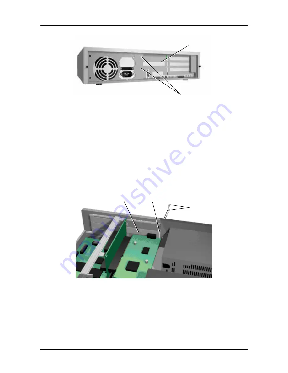
Figure Section 3-10 Removing the Slot Cover Support Screws
4.
Hold the board by its edges, component side down and the bracket end facing the
rear of the unit, and insert it into the expansion slot.
Press the board firmly into the expansion slot connector. Gently rock the board
from side-to-side to seat it into the connector.
5.
Hold the slot cover support over the expansion board bracket and replace the two
screws removed earlier (see Figure Section 3-12). The slot cover support secures
the expansion board in place.
Figure Section 3-12 Attaching the Slot Cover Support
6.
Attach any signal cables required by the expansion board.
7.
Replace the system unit cover.
Slot Cover
Slot Cover Support
Screws
Screws
Expansion Board
Bracket
Slot Cover
Support


