background image

EN-11

•  Do not unplug the power cord from the projector or the power outlet 

while projecting. Doing so could cause deterioration of the projec-

tor’s AC IN terminal or power plug contact. To interrupt the AC power 

supply while images are being projected, use a breaker, etc.

•  About handling of the remote control

-  The remote control will not work if the projector’s remote signal 

sensor or the remote control’s signal transmitter is exposed to 

strong light or if there are obstacles between them that obstruct 

the signals.

-  Operate the remote control from within 20 meters from the projec-

tor, pointing it at the projector’s remote signal sensor.

-  Do not drop the remote control or handle it improperly.

-  Do not let water or other liquids get on the remote control. Should 

the remote control get wet, wipe it off immediately.

-  Avoid using in hot and humid places as far as possible.

-  When planning not to use the remote control for long periods of 

time, remove both batteries.

•  Take measures to prevent external light from shining on the screen.

  Make sure only the light from the projector shines on the screen. The 

less external light on the screen, the higher the contrast and the more 

beautiful the images.

•  About screens

  Images will not be clear if there is dirt, scratches, discoloration, etc. on 

your screen. Handle the screen with care, protecting it from volatile 

substances, scratches and dirt.

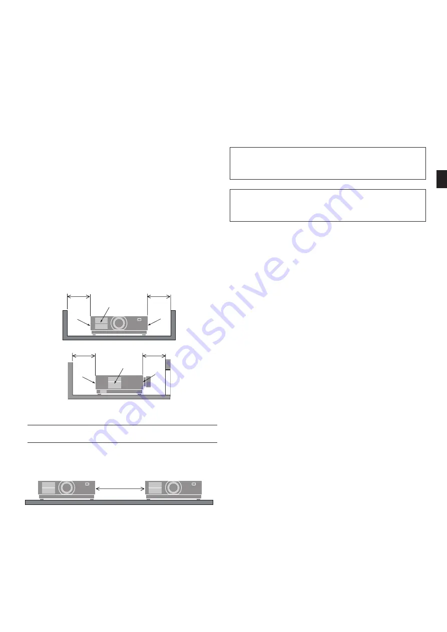
Clearance for Installing the Projector

•  When installing the projector, keep sufficient space around it, as 

described below. If not, the hot exhaust emitted from the projector 

may be taken back in.

  Also, make sure no wind from an air-conditioner hits the projector.

  The projector’s heat control system may detect an abnormality (tem-

perature error) and automatically shut off the power.

c

c

a

a

a

a

a

b

c

d

c

c

a

a

a

a

a

b

c

d

a: Intake vent / b: Exhaust vent / c: 20 cm/8” or greater /  

d: 30 cm/12” or greater

NOTE:
•  In the above figure, it is assumed that there is sufficient space above the projector.

•  When using multiple projectors together, provide sufficient space 

around the projectors for air intake and exhaust. When the intake and 

exhaust vents are obstructed, the temperature inside the projector 

will rise and this may result in a malfunction. 

About Copyright of original projected pictures:

Please note that using this projector for the purpose of commercial gain 

or the attraction of public attention in a venue such as a coffee shop or 

hotel and employing compression or expansion of the screen image 

with the following functions may raise concern about the infringement 

of copyrights which are protected by copyright law.

[ASPECT RATIO], [KEYSTONE], Magnifying feature and other similar 

features.

Power management function

The projector has power management functions. To reduce power 

consumption, the power management functions (1 and 2) are factory 

preset as shown below. To control the projector from an external device 

via a LAN or serial cable connection, use the on-screen menu to change 

the settings for 1 and 2.

1.  STANDBY MODE (Factory preset: NORMAL)

To control the projector from an external device, select [NET-
WORK STANDBY] or [SLEEP] for [STANDBY MODE].

2.  AUTO POWER OFF (Factory preset: 1 hour)

To control the projector from an external device, select [OFF] for 
[AUTO POWER OFF].

Summary of Contents for PV800UL-W

Page 1: ...English Fran ais Espa ol Portugu s Projector PV800UL W PV800UL B PV710UL W PV710UL B Important Information EN FR ES PT TW...

Page 2: ...P PV710UL B ES Este documento Informaci n importante cubre nicamente la informaci n relacionada con la seguridad y las precauciones del proyector El manual del usuario y el manual de instalaci n est n...

Page 3: ...t valid Guarantee Policy on our Web Site https www sharpnecdisplays eu For Customers in U K IMPORTANT The wires in this mains lead are coloured in accordance with the following code GREEN AND YELLOW E...

Page 4: ...is symbol indicates things you must do This symbol indicates something that must not be got wet This symbol indicates that the power cord should be un plugged from the power outlet Safety Cautions WAR...

Page 5: ...hese requirements Use a power outlet as the projector s power supply Do not connect the projector directly to electrical light wiring Doing so is dangerous Handling the power cord REQUIRED Please use...

Page 6: ...DO NOT perform installation work by people other than installers Doing so may result in the projector falling and causing injury We are not liable for any accident or and damage resulting from improp...

Page 7: ...reaction control in nuclear facility medical life support system and missile launch control in a weapon system CAUTION Power supply Connecting the power cord to earth REQUIRED This equipment is design...

Page 8: ...uch the exhaust vent area while projecting or immediately after projecting images The exhaust vent area may be hot at this time and touching it could cause burns CAUTION FOR HIGH TEMPERATURE Moving th...

Page 9: ...W PV710UL B Light Module A light module containing multiple laser diodes is equipped in the product as the light source These laser diodes are sealed in the light module No maintenance or service is...

Page 10: ...ctor Lens model name The lens unit model is listed at one of the locations in in the im ages below Diagram of NP44ML Diagram of non NP44ML models Combining with Risk group 3 category products Projecto...

Page 11: ...r to keep the installation manual user s manual and inspection records in an easy to reach place Instruct them to determine whether the projector conforms to the standards of each country and region C...

Page 12: ...installing the projector please see the Installation Manual pro vided on our web site see the back of the cover 1 To prevent the projector from falling install it on the ceiling in a way with sufficie...

Page 13: ...exhaust emitted from the projector may be taken back in Also make sure no wind from an air conditioner hits the projector The projector s heat control system may detect an abnormality tem perature err...

Page 14: ...EN 12...

Page 15: ...tats Unis Pour l UE 7N080242 7N080028 Cordon d alimentation But e du cordon d alimentation 24F53221 24F53232 Sangle 24F54153 Vis de protection contre le vol de l objectif 24V00941 Documents Informatio...

Page 16: ...ue chose qui doit tre interdit Ce symbole indique des choses que vous devez faire Cesymboleindiquequelquechosequinedoitpas tremouill Ce symbole indique que le cordon d alimentation doit tre d branch d...

Page 17: ...xigences Utilisez une prise de courant comme source d alimentation du projecteur Ne connectez jamais le projecteur directement au c blage lectrique Cela est dangereux Manipulation du cordon d alimenta...

Page 18: ...actez votre fournisseur D BRANCHER LE CORDON D ALIMENTATION Installation suspendue au plafond ATTENTION Consultez votre fournisseur pour installer le projecteur au plafond Des comp tences sp ciales so...

Page 19: ...accompagn e de risques ou de dangers mortels qui peuvent directement entra ner la mort des blessures corporelles des dommages physiques graves ou d autres pertes y compris le contr le de r action nucl...

Page 20: ...vacuation pendant la projection ou imm diatement apr s la projection d images La zone de l vent d vacuation peut tre chaude ce moment l et la toucher peut provoquer des br lures ATTENTION HAUTE TEMP...

Page 21: ...ongueur d onde 455 nm Puissance maximale 176 W PV800UL W PV800UL B 154 W PV710UL W PV710UL B Module d clairage Un module d clairage contenant plusieurs diodes lasers quipe le produit comme source de l...

Page 22: ...ller le projecteur Nom du mod le d objectif Le mod le d objectif est indiqu l un des emplacements dans dans les images ci dessous Sch ma du NP44ML Sch ma des mod les non NP44ML Combinaison avec les pr...

Page 23: ...rez vous que des mesures de s curit appropri es ont t prises lors de l utilisation du projecteur du r glage de la lumi re etc V rifiez si la zone de s curit appropri e pour l objectif install a t corr...

Page 24: ...er la corrosion des parties m talliques ou un dysfonctionnement l intention du fournisseur et de l installateur Pour l installation du projecteur veuillez consulter le Manuel d installa tion fourni su...

Page 25: ...es des rayures et de la salet D gagement pour l installation du projecteur Lorsque vous installez le projecteur gardez un espace suffisant au tour de lui comme d crit ci dessous Sinon l air chaud mis...

Page 26: ...FR 12...

Page 27: ...o de enchufe Para Estados Unidos Para la Uni n Europea 7N080242 7N080028 Cable de alimentaci n Tope del cable de alimentaci n 24F53221 24F53232 Correa 24F54153 Tornillo antirrobo de la lente 24V00941...

Page 28: ...Este s mbolo indica algo que debe estar prohibido Este s mbolo indica acciones que debe realizar Este s mbolo indica algo que no se debe mojar Este s mbolo indica que el cable de alimentaci n se debe...

Page 29: ...isitos Use una toma de corriente como suministro de alimentaci n del proyector No conecte el proyector directamente al cableado el ctrico de iluminaci n Hacerlo es peligroso Manipulaci n del cable de...

Page 30: ...n en el techo NO permita que personas que no sean instaladores realicen las tareas de instalaci n De lo contrario el proyector podr a caerse y causar lesiones No nos hacemos responsables por cualquie...

Page 31: ...dica y el control de lanzamiento de misiles en un sistema armament stico PRECAUCI N Suministro de alimentaci n Conexi n del cable de alimentaci n a una toma de tierra REQUERIDO Este equipo ha sido di...

Page 32: ...que la zona de la rejilla de escape durante o inmediatamente despu s de la proyecci n La zona de la rejilla de escape puede estar caliente en este momento y tocarla podr a causar quemaduras PRECAUCI N...

Page 33: ...l producto como fuente de luz Estos diodos l ser est n sellados en el m dulo de iluminaci n No se necesita mantenimiento ni inspecci n para el funcionamiento del m dulo de iluminaci n El usuario final...

Page 34: ...odelo del objetivo se indica en una de las ubicaciones en en las im genes siguientes Diagrama del NP44ML Diagrama de modelos que no sean NP44ML Combinaci n con productos de categor a del grupo de ries...

Page 35: ...uridad para cada lente Aseg rese de que se han tomado las medidas de seguridad ade cuadas al utilizar el proyector al ajustar la luz etc Compruebe si la zona de seguridad apropiada para la lente insta...

Page 36: ...o de funcionamiento Para el distribuidor y el instalador Al instalar el proyector consulte el Manual de instalaci n suministrado en nuestro sitio web consulte la parte posterior de la cubierta 1 Para...

Page 37: ...vol tiles ara azos y suciedad Espacio libre para la instalaci n del proyector Cuando instale el proyector deje suficiente espacio alrededor de este como se describe a continuaci n De lo contrario el...

Page 38: ...ES 12...

Page 39: ...ugue Para os EUA Para a UE 7N080242 7N080028 Cabo de alimenta o Fixador do cabo de alimenta o 24F53221 24F53232 Al a 24F54153 Parafuso de preven o contra roubo da lente 24V00941 Documentos Informa o i...

Page 40: ...go que deve ser proibido Este s mbolo indica coisas que voc deve fazer Este s mbolo indica algo que n o deve ser molhado Este s mbolo indica que o cabo de alimenta o deve ser des conectado da tomada P...

Page 41: ...ifique se a fonte de alimenta o qual ele ser conectado atende a esses requisitos Use uma tomada como a fonte de alimenta o do projetor N o conecte o projetor diretamente fia o el trica Isso perigoso M...

Page 42: ...ssoas que n o sejam os instaladores Fazer isso poder resultar na queda do projetor e causar ferimentos N o somos respons veis por qualquer acidente ou e dano resultante de uma instala o ou um manuseio...

Page 43: ...co de suporte vida e controle de lan amento de m sseis em um sistema de armas CUIDADO Fonte de alimenta o Conectar o cabo de alimenta o ao fio terra NECESS RIO Este equipamento foi planejado para ser...

Page 44: ...e na rea da sa da de ar enquanto projeta ou imediatamente ap s projetar imagens A rea da sa da de ar pode estar quente nesse momento e toc la pode provocar queimaduras CUIDADO COM A ALTA TEMPERATURA M...

Page 45: ...e Luz Um m dulo de luz contendo diversos diodos a laser est instalado no produto como a fonte de luz Esses diodos de laser est o lacrados no m dulo de luz N o neces s ria nenhuma manuten o ou reparo p...

Page 46: ...odelo da lente O modelo da unidade de lente est listado em um dos locais em nas imagens abaixo Diagrama do NP44ML Diagrama dos modelos n o NP44ML Combinando com produtos de categoria do Grupo de Risco...

Page 47: ...erifique se as devidas medidas de seguran a foram tomadas ao operar o projetor ajustar a luz etc Verifique se a zona de seguran a apropriada para a lente instalada foi assegurada corretamente Verifiqu...

Page 48: ...as de metal ou mau funcionamento Para o revendedor e o instalador Ao instalar o projetor consulte o Manual de Instala o fornecido em nosso site veja na parte de tr s da tampa 1 Para evitar que o proje...

Page 49: ...o vento do ar condicionado n o atinge o projetor O sistema de controle de calor do projetor pode detectar uma anormalidade erro de temperatura e desligar automaticamente a alimenta o c c a a a a a b c...

Page 50: ...PT 12...

Page 51: ...TW 1 24F53241 7N901322 4 x2 7N080242 7N080028 24F53221 24F53232 24F54153 24V00941 TINS 0003VW01 TINS 0004VW01 TINS 0004VW01 TINS 0005VW01 https www sharpnecdisplays eu...

Page 52: ...TW 2...

Page 53: ...TW 3 1 2 3 1 3 2 IEC EN 62471 5 2 3 3 TW 8 TW 7 100 240 V AC 50 60 Hz...

Page 54: ...TW 4...

Page 55: ...TW 5 2 AC IN...

Page 56: ...TW 6 Ethernet HDBaseT LAN Ethernet HDBaseT LAN TW 10 0 C 45 C 32 F 113 F 20 80 10 C 50 C 14 F 122 F 20 80...

Page 57: ...ZL 6 4 4 0 6 4 9 7 6 1 9 7 NP40ZL 31 7 23 8 31 7 41 0 31 8 41 0 NP41ZL 13 0 9 4 13 0 27 9 20 7 27 9 NP43ZL 6 8 4 9 6 8 13 4 9 7 13 4 NP50ZL 42 0 32 7 42 0 48 2 38 6 48 2 HC HR HL HC VU VC VD NP11FL 21...

Page 58: ...2471 5 2 3 2 RG2 RG2 IEC EN 62471 5 2015 3 RG3 IEC EN 62471 5 RG3 RG3 RG3 IEC EN 62471 5 2015 NP44ML NP44ML 3 PV800UL W PV800UL B PV710UL W PV710UL B NP15ZL NP43ZL IEC EN 62471 5 2015 3 RG3 Diagram 1...

Page 59: ...TW 9 EMI 2006 66 EC...

Page 60: ...TW 10 1 2 3 4 5 200 1 600 AC IN 20 c c a a a b d c c a a a a a b c d a b c 20 8 d 30 12...

Page 61: ...B PBDE 1 2 NP PV800UL W NP PV800UL B NP PV710UL W NP PV710UL B 16 10 WUXGA 1920 1200 8 000 lm 7 100 lm 100 240 V 50 60 Hz 6 1 A 100 130 V 2 5 A 200 240 V 5 3 A 100 130 V 2 2 A 200 240 V 167 7 02 8500...

Page 62: ...TW 12...

Page 63: ...0 13 NP43ZL g 0 7 0 23 0 15 h 1 2 0 21 0 13 EN a Screen b Hazard zone c Precautionary zone d Floor e Lens f Hazard zone unit m g Wide h Tele FR a cran b Zone risque c Zone de pr caution d Sol e Objec...

Page 64: ...ort thedrgroup co nz In Asia Sharp NEC Display Solutions Ltd Address 686 1 Nishioi Oi Machi Ashigarakami Gun Kanagawa 258 0117 Japan Telephone 81 465 85 2369 Sharp NEC Display Solutions China Ltd Addr...

Reviews: