Installation Guide
QX-S6600 Series Ethernet Switches
5-6
a service port. When a 1/10-GE Ethernet ports/SFP+/QSFP+ port is bound to an IRF
port, other 1/10-GE Ethernet ports/SFP+/QSFP+ ports in the same port group cannot
be used as service ports, and vice versa.
A common practice is to use one 1/10-GE Ethernet ports/SFP+ port group for IRF
connections, and bind every two 1/10-GE Ethernet ports/SFP+ ports in the group to an IRF
port for increased bandwidth and availability.
5.2.5 Planning the cabling scheme
For the QX-S6648XP-6Q, use SFP+/QSFP+ cables or SFP+/QSFP+ transceiver modules
and fibers to connect the IRF member switches.
For the QX-S6648XT-6Q, use twisted pair cables, QSFP+ cables or QSFP+ transceiver
modules and fibers to connect the IRF member switches.
For the QX-S6632QP, QSFP+ cables or QSFP+ transceiver modules and fibers to connect
the IRF member switches.
If the IRF member switches are far away from one another, choose the SFP+/QSFP+
transceiver modules with optical fibers. If the IRF member switches are all in one
equipment room, choose twisted pair/SFP+/QSFP+ cables. For more information about
available SFP+/QSFP+ cables and transceiver modules, see "
SFP+ port
" and "
QSFP+
port
."
The following subsections describe several NEC recommended IRF connection schemes,
and all these schemes use a ring topology.
I.
Connecting the IRF member switches in one rack
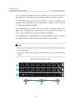
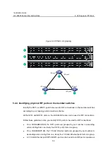
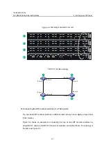
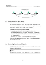
Figure 5-4 shows an example for connecting four IRF member switches in a rack by using
QSFP+ cables and QSFP+ transceiver modules and optical fibers. The switches in the ring
topology (see Figure 5-5) are in the same order as connected in the rack.

