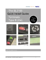
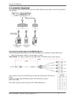
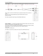
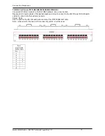
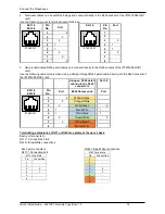
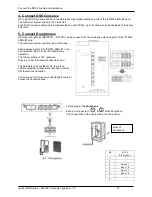
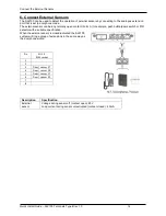
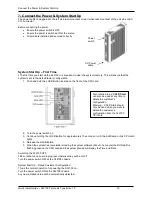
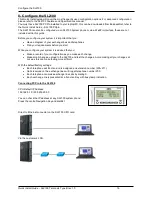
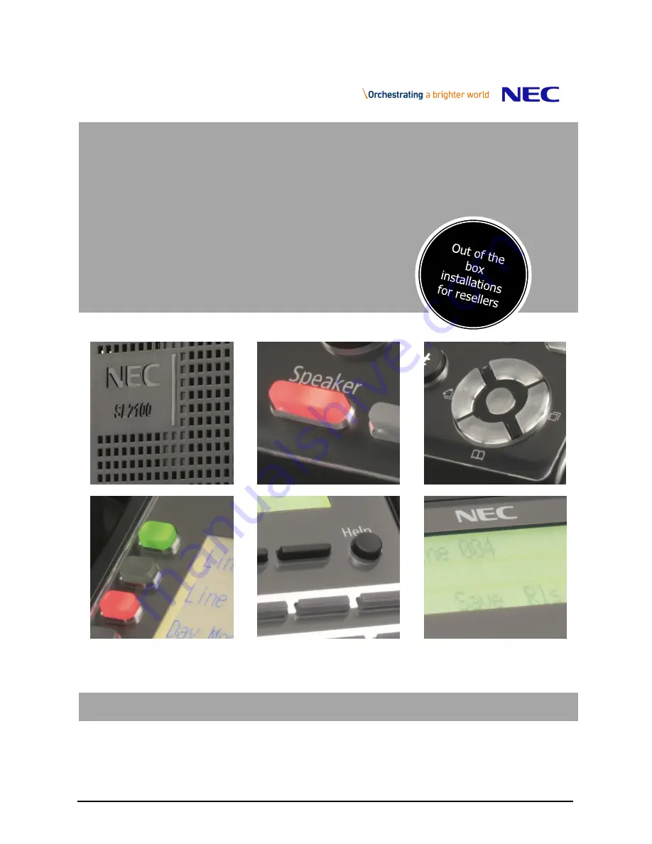
background image

Quick Install Guide 

– SL2100 Terminals Type B rev 1.0          

     1 


The SL2100 

Quick Install Guide: 

Terminals 
Type B (2w)


www.nec-enterprise.com


Summary of Contents for UNIVERGE SL2100

Page 1: ...Quick Install Guide SL2100 Terminals Type B rev 1 0 1 The SL2100 Quick Install Guide Terminals Type B 2w www nec enterprise com...

Page 2: ...ace card Further information is available on BusinessNet Please keep all information supplied for future reference Regulatory Notice Refer to the Declaration of Conformity Regulatory and Safety Consid...

Page 3: ...extensions at RJ11 or RJ45 face plates at the user s desk 12 4 Connect DSS Consoles 13 5 Connect Doorphones 13 6 Connect External Sensors 14 7 Connect the Power System Start Up 15 8 Configure the SL2...

Page 4: ...W 008U C1 4 wire connection Type B IP7WW 082U B1 2 wire connection This guide also includes details of installing the external Music on Hold Background Music Paging and Relay connections as these are...

Page 5: ...h pre installed IP licenses and 2hour InMail IP7WW 082U B1 8 Digital Extension 2wire and 2 SLT extension card 8 digital and 2 SLT extension interfaces max 3 per unit IP7WW 008U C1 8 Hybrid Extensions...

Page 6: ...can be installed but will only support the two analogue extensions and any trunk daughter card SL2100 Capacity Item Maximum capacity in a single chassis TDM Trunks 42 There is a trade off between each...

Page 7: ...ditional Items Required Cross head screwdriver Utility knife or small cutters to remove the plastic knockouts Solid wire for extending telephone cabling Recommended cable type Twisted pair CW1308 or s...

Page 8: ...I circuit 30 trunk channels Each IP7WW 082U B1 card can have one daughter card mounted If you are connecting a doorphone unit then you must set the hardware links before mounting a trunk daughter card...

Page 9: ...t these interfaces into the customer s building infrastructure 1 Use the cable assembly adapter or panel available from NEC Cable LPNEC4 2m length converts a four port RJ45 socket to four RJ45 plugs o...

Page 10: ...d for the SLI socket of the IP7WW 082U B1 card Adapter ADNEC14 Converts a four port RJ45 socket to four RJ45 sockets one port per socket Requires five patch cables of the desired length and colour Can...

Page 11: ...one port per socket Requires 4 6 12 patch cables of the desired length and colour to connect to the SL2100 plus 16 24 40 patch cables to connect into the customer s panels Colour black Can be used fo...

Page 12: ...hen using a straight through RJ45 patch cable directly into the RJ45 sockets of the IP7WW 082U B1 card Using an RJ45 patch cable into the RJ45 connectors SLI 1 2 ESI 1 4 ESI 5 8 Pin No Port RJ45 Colou...

Page 13: ...extension ports of the IP7WW 082U B1 card The maximum system capacity is 6 doorphones Each analogue port of the IP7WW 082U B1 card has hardware links to select SLT doorphone operation The factory sett...

Page 14: ...lly open contact Form A for example push button panic switch or PIR detector with a suitable specification When the external sensor is closed activated the SL2100 system will ring a group of extension...

Page 15: ...holding the LOAD Button for approximately 10 seconds or until the ALM lamp on the CPU card lights 4 Release the LOAD Button 5 When the system has completed reloading the system software about one minu...

Page 16: ...your requirements before you start While you configure your system it is advised that you Make a record of your configuration as you make each change Make small changes upload to the SL2100 and test t...

Page 17: ...Guide SL2100 Terminals Type B rev 1 0 17 SL2100 PCPro Installer level access User Name tech Password 12345678 On first install you may need to setup the default sliding panes if you wish to use these...

Page 18: ...alled within the SL2100 system IP7WW 308U A1 card Clicking on any of the interfaces will show the appropriate Properties Pane where you can configure the selected port Audio and Paging Digital extensi...

Page 19: ...t the DSS console when it s connected 1 Go to the Chassis View and click the DSS console 2 Assign the console to the extension that it will be used with 3 Setup the keys of the DSS console Click the D...

Page 20: ...dit the Operator number within Easy Edit System Numbering Plan System Numbering you will need to select level 3 details view The Operator extension that is the target of the pilot number is defined in...

Page 21: ...Description Setting Timer setting Minimum Break Time 1 255 5 1275mS 5mS increment Maximum Break Time 1 255 5 1275mS 5mS increment Minimum Make Time 1 255 5 1275mS 5mS increment Maximum Make Time 1 25...

Page 22: ...me The minimum duration of a ground flash 21 105mS Minimum Off hook Time The minimum time for an off hook duration 19 95mS No Detection Time after Off hook The duration after off hook before dialling...

Page 23: ...Description Function Default Minimum Break Time The minimum duration of a dial pulse break 2 10mS Maximum Break Time The maximum duration of a dial pulse break 10 50mS Set to 13 65mS when TBR is requ...

Page 24: ...set this timer to 14 70mS Maximum Hook Flash Time The maximum duration of a Hook Flash Time Break Recall TBR 25 125mS For Time Break Recall detection set this timer to 25 125mS Note You must also set...

Page 25: ...can be either analogue telephone Doorphone or External sensor The port is setup by hardware switched on the IP7WW 082U B1 card refer to the Quick Install Guide for MOH and External Audio for details...

Page 26: ...re apply Then Upload your changes to the SL2100 and re test Tip Press F1 to get help within PCro If you can t locate your errors within PCPro then you may need to default the SL2100 back to factory d...

Reviews: