background image

Programming Manual

NECIC-AP-002

Issue 10.1(R9.5)

Summary of Contents for Univerge SV8100

Page 1: ...Programming Manual NECIC AP 002 Issue 10 1 R9 5 ...

Page 2: ...mployees and customers The information contained herein is the property of NEC Corporation and shall not be reproduced without prior written approval of NEC Corporation Dterm is a registered trademark of NEC Corporation UNIVERGE is a trademark of NEC Corporation Windows is a registered trademark of Microsoft Corporation Copyright 2008 2014 NEC Corporation Printed in Japan ...

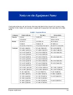
Page 3: ...DTL 6DE 1A BK TEL DTL 12D 1 BK TEL DTL 12D 1P BK TEL DTL 12D 1A BK TEL DTL 12D 1 WH TEL DTL 12D 1P WH TEL DTL 24D 1 BK TEL DTL 24D 1P BK TEL DTL 24D 1A BK TEL DTL 24D 1 WH TEL DTL 24D 1P WH TEL DTL 32D 1 BK TEL DTL 32D 1P BK TEL DTL 32D 1A BK TEL DTL 8LD 1 BK TEL DTL 8LD 1P BK TEL DTL 8LD 1A BK TEL DTL 8LD 1 WH TEL DTL 8LD 1P WH TEL DTL 12PA 1 BK TEL DTL 12PA 1P BK TEL DTL 12PA 1A BK TEL DTL 12BT ...

Page 4: ... ADA LP UNIT ADA LA UNIT ILPA R UNIT ILPA RP UNIT ILPA RA UNIT BCH L BK UNIT BCH LP BK UNIT BCH LA BK UNIT BHA L UNIT BHA LP UNIT BHA LA UNIT PSA L BK UNIT PSA LP BK UNIT PSA LA BK UNIT PSA L WH UNIT PSA LP WH UNIT DCL 60 1 BK CONSOLE DCL 60 1P BK CONSOLE DCL 60 1A BK CONSOLE DCL 60 1 WH CONSOLE DCL 60 1P WH CONSOLE 8LK L BK UNIT 8LK LP BK UNIT 8LK LA BK UNIT 8LK L WH UNIT 8LK LP WH UNIT GBA L GBA...

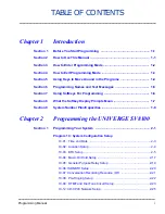
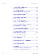
Page 5: ...e Programs 1 4 Section 6 Programming Names and Text Messages 1 5 Section 7 Using Softkeys For Programming 1 6 Section 8 What the Softkey Display Prompts Mean 1 7 Section 9 System Number Plan Capacities 1 8 Chapter 2 Programming the UNIVERGE SV8100 Section 1 Programming Your System 2 1 Program 10 System Configuration Setup 10 01 Time and Date 2 3 10 02 Location Setup 2 4 10 03 ETU Setup 2 5 10 04 M...

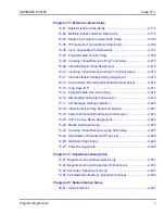
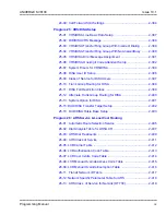
Page 6: ...efix Setup 2 44 10 26 IP System Operation Setup 2 45 10 27 H 323 System Interconnection w Application Setup OT 2 46 10 28 SIP System Information Setup 2 47 10 29 SIP Server Information Setup 2 49 10 30 SIP Authentication Information Setup 2 52 10 31 Networking Keep Alive Setup OT 2 53 10 32 Networking Maximum PRI Channel Setup OT 2 55 10 33 SIP Registrar Proxy Information Basic Setup 2 56 10 36 SI...

Page 7: ...on Numbering 2 96 11 04 Virtual Extension Numbering 2 98 11 06 ACI Extension Numbering 2 100 11 07 Department Group Pilot Numbers 2 101 11 08 ACI Group Pilot Number 2 102 11 09 Trunk Access Code 2 103 11 10 Service Code Setup for System Administrator 2 105 11 11 Service Code Setup for Setup Entry Operation 2 108 11 12 Service Code Setup for Service Access 2 112 11 13 Service Code Setup for ACD 2 1...

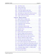
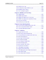
Page 8: ...ensions 2 139 13 04 Speed Dialing Number and Name 2 140 13 05 Speed Dial Trunk Group 2 143 13 07 Telephone Book Dial Number and Name 2 144 13 08 Telephone Book System Name 2 145 13 09 Telephone Book Group Name 2 146 13 10 Telephone Book Routing 2 147 Program 14 Trunk Basic Setup 14 01 Basic Trunk Data Setup 2 149 14 02 Analog Trunk Data Setup 2 156 14 04 Behind PBX Setup 2 159 14 05 Trunk Group 2 ...

Page 9: ...al Extension Delayed Ring Assignment 2 215 15 12 Conversation Recording Destination for Extensions 2 216 15 13 Loop Keys OT 2 217 15 14 Programmable One Touch Keys 2 218 15 16 SIP Register ID Setup for Extension 2 219 15 17 CO Message Waiting Indication 2 220 15 18 Virtual Extension Key Enhanced Options 2 221 15 19 System Telephone Book Setup for Extension 2 223 15 20 LCD Line Key Name Assignment ...

Page 10: ...ce Options Charging Cost Service 2 260 20 13 Class of Service Options Supplementary Service 2 261 20 14 Class of Service Options for DISA E M 2 267 20 15 Ring Cycle Setup 2 269 20 16 Selectable Display Messages 2 271 20 17 Operator Extension 2 274 20 18 Service Tone Timers 2 275 20 19 System Options for Caller ID 2 277 20 20 Message Setup for Non Caller ID Data 2 279 20 21 System Options for Long ...

Page 11: ...tensions 2 315 21 05 Toll Restriction Class 2 316 21 06 Toll Restriction Table Data Setup 2 321 21 07 Toll Restriction Override Password Setup 2 323 21 08 Repeat Dial Setup 2 324 21 09 Dial Block Setup 2 325 21 10 Dial Block Restriction Class Per Extension 2 326 21 11 Extension Ringdown Hotline Assignment 2 327 21 12 ISDN Calling Party Number Setup for Trunks 2 328 21 13 ISDN Calling Party Number ...

Page 12: ...ation Number Conversion 2 356 22 12 DID Intercept Ring Group 2 361 22 13 DID Trunk Group to Translation Table Assignment 2 363 22 14 VRS Delayed Message for IRG 2 364 22 15 VRS Delayed Message for Department Group 2 366 22 16 Private Call Refuse Target Area Setup 2 368 22 17 Dial In Conversion Table Area Setup for Time Pattern 2 369 22 18 Private Call Assignment Setup 2 370 22 19 DID MFC Dialing O...

Page 13: ...p 2 396 25 09 Class of Service for DISA Users 2 397 25 10 Trunk Group Routing for DISA 2 398 25 11 DISA Toll Restriction Class 2 399 25 12 Alternate Trunk Group Routing for DISA 2 400 25 13 System Option for DISA 2 401 25 15 DUD DISA Transfer Target Setup 2 402 25 16 DUD DISA Talkie Base Setup 2 403 Program 26 ARS Service Least Cost Routing 26 01 Automatic Route Selection Service 2 405 26 02 Dial ...

Page 14: ... 31 03 Internal Paging Group Settings 2 438 31 04 External Paging Zone Group 2 441 31 05 Universal Night Answer Ring Over Page 2 442 31 06 External Speaker Control 2 443 31 07 Combined Paging Assignments 2 445 31 08 BGM on External Paging 2 446 Program 32 Door Box and Sensor Setup 32 01 Door Box Timers Setup 2 447 32 02 Door Box Ring Assignment 2 448 32 03 Door Box Basic Setup 2 449 32 04 Door Box...

Page 15: ...Verified Account Code Table 2 476 Program 40 Voice Recording System 40 07 Voice Prompt Language Assignment for VRS 2 477 40 10 Voice Announcement Service Option 2 479 40 11 Preamble Message Assignment 2 481 Program 41 ACD Setup 41 01 System Options for ACD 2 483 41 02 ACD Group and Agent Assignments 2 484 41 03 Incoming Ring Group Assignment for ACD Group 2 485 41 04 ACD Group Supervisor 2 486 41 ...

Page 16: ...el 2 515 42 02 Hotel Motel Telephone Setup 2 518 42 03 Class of Service Options Hotel Motel 2 520 42 04 Hotel Mode One Digit Service Codes 2 522 42 05 Hotel Room Status Printer 2 523 42 06 PMS Service Setting 2 524 42 07 PMS Restriction Level Conversion Table 2 526 42 08 Text Message Setup for Hotel Room Status 2 527 42 09 Flexible Setup for Room Status 2 529 Program 44 ARS F Route Setup 44 01 Sys...

Page 17: ...ns 2 576 47 08 Call Routing Mailbox Options 2 579 47 09 Announcement Mailbox Options 2 581 47 10 VM8000 InMail Trunk Options 2 583 47 11 VM8000 InMail Answer Table Options 2 586 47 12 VM8000 InMail Answer Schedules 2 590 47 13 VM8000 InMail Dial Action Tables 2 599 47 15 Routing Directory Mailbox Options 2 607 47 16 InMail Language License 2 608 47 17 Routing Distribution Mailbox Options 2 611 47 ...

Page 18: ...ment 2 637 50 14 CCIS Intercom Digits for Caller ID Call Return 2 638 50 15 CCIS over IP Basic Information Setting 2 639 Program 51 NetLink Service 51 01 NetLink System Property Setting 2 641 51 02 NetLink System Individual Setting 2 643 51 03 NetLink Internet Protocol Address List Setting 2 645 51 04 IP Address Setting of Top Priority Primary System of NetLink 2 647 51 05 NetLink Timer Settings 2...

Page 19: ...up OT 2 688 80 09 Short Ring Setup 2 689 80 11 MFC Tone Receiver Setup OT 2 692 Program 81 Basic Hardware Setup for Trunk 81 01 COT Initial Data Setup 2 695 81 02 DIOPU Initial Data Setup 2 698 81 03 ODT Initial Data Setup 2 700 81 04 ISDN BRI Layer 1 T Point Initial Data Setup 2 702 81 05 ISDN BRI PRI Layer 2 T Point Initial Data Setup 2 703 81 06 ISDN BRI PRI Layer 3 T Point Timer Setup 2 705 81...

Page 20: ...p for Multi Line Telephone 2 754 82 15 OPX CODEC QSLAC Filter Data Setup 2 755 82 16 SLI CODEC QSLAC Filter Data Setup 2 758 82 17 CODEC Filter Option Data Type Setup 2 761 Program 84 Hardware Setup for VoIP 84 01 H 323 Trunk Basic Information Setup 2 763 84 02 H 225 and H 245 Information Basic Setup 2 768 84 03 IP Phone Information Basic Setup 2 770 84 07 Firmware Download Setup 2 772 84 08 Firmw...

Page 21: ...Fixed Mode Setup 2 835 84 31 VoIPDB Echo Canceller Setup 2 837 84 32 FAX Over IP CODEC Setup 2 844 Program 85 Hardware Setup for ETIA Switch 85 01 ETIA LAN Setup AU 2 847 85 02 ETIA VLAN Setup AU 2 849 85 03 Priority Setup AU 2 851 85 04 Port Mirroring Setup AU 2 853 85 05 ETIA VLAN Group Settings AU 2 854 Program 90 Maintenance Program 90 01 Installation Date 2 857 90 02 Programming Password Setu...

Page 22: ...Information 2 895 90 35 Wizard Programming Level Setup 2 896 90 36 Firmware Update Time Setting 2 897 90 37 Set Temporary License AU 2 899 90 38 User Programming Data Level Setup 2 900 90 39 Virtual Loop Back Port Reset 2 903 90 41 Server Setting to Update Terminal Local Data 2 904 90 42 DT700 Multiline Terminal Version Information 2 905 90 43 Deleting Terminal License of DT700 2 906 90 44 Deletin...

Page 23: ...MP Setup 2 925 90 65 1st Party CTI Authentication Password Setup 2 926 90 68 Side Tone Auto Setup 2 927 90 69 Outbound IP Connection Setup 2 928 Program 92 Copy Program 92 01 Copy Program 2 929 92 02 Delete All Extension Numbers 2 933 92 03 Copy Program by Port Number 2 934 92 04 Extension Data Swap 2 935 92 05 Extension Data Swap Password 2 938 92 06 Fill Command 2 939 92 07 Delete Command 2 941 ...

Page 24: ... On Off Timing Pattern 2 183 Table 2 5 Program 15 02 Incoming Signal Frequency Patterns 2 184 Table 2 6 Program 15 08 Incoming Signal Frequency Patterns 2 211 Table 2 7 Ringing Cycles 2 270 Table 2 8 Program 22 03 Incoming Signal Frequency Patterns 2 345 Table 2 9 LED Patterns for DSS Console 2 433 Table 2 10 47 02 16 Default Table 2 567 Table 2 11 47 06 14 Default Table 2 574 Table 2 12 47 07 03 ...

Page 25: ... marked with AU apply only for Australia Features marked with OT apply for General Overseas SECTION 2 HOW TO USE THIS MANUAL This section lists each program in numerical order For example Program 10 01 is at the beginning of the section and Program 92 01 is at the end The information on each program is subdivided into the following headings Description describes what the program options control Th...

Page 26: ...you to enter the programming mode dial 150701 from the telephone dial pad After you do you will see the message 15 07 01 TEL on the first line of the telephone display This indicates the program number 15 07 item number 01 and that the options are being set for the extension The second row of the display KY01 01 indicates that Key 01 is being programmed with the entry of 01 The third row allows yo...

Page 27: ...Note that a USB Drive can only hold one customer database Each database to be saved requires a separate drive Password User Name Level Programs at this Level nec i 1 MF Manufacture Level MF 20 12 AU 40 04 AU 40 07 80 02 OT 80 11 OT 81 04 81 05 82 01 AU 82 03 AU 82 04 AU 82 05 82 08 12345678 tech 2 IN Installation IN All programs in this section not listed for MF SA SB 0000 ADMIN1 3 SA System Admin...

Page 28: ...Answer again allows you to select a new program in the 15 XX series Pressing Answer a third time allows you to enter a new program beginning with 1 Pressing Answer one last time brings you to the beginning program display allowing you to enter any program number MIC Switch between the different input data fields by pressing MIC The cursor moves up to the top row of the display Pressing MIC again m...

Page 29: ...n Permit Table If you enter data and then press this key the system accepts the data before scrolling forward VOL Scroll forward through a list of entry numbers e g from extension etc or through entries in a table e g Common Permit Table If you enter data and then press this key the system accepts the data before scrolling backward Table 1 1 Keys for Entering Data Continued Keys for Entering Data ...

Page 30: ...ange accordingly Pressing the VOLUME or VOLUME will scroll between the menus Enter characters B E S Accepts an entry only required if two letters on the same key are needed ex TOM Pressing again Space In system programming mode use the right arrow Softkey instead to accept and or add a space Recall Clear the character entry one character at a time Hold Clear all the entries from the point of the f...

Page 31: ...ompts Softkey Display Prompts If you press this Softkey The system will back Go back one step in the program display You can press VOLUME or VOLUME to scroll forward or backward through a list of programs Scroll down through the available programs Scroll up through the available programs select Select the currently displayed program Move the cursor to the left Move the cursor to the right 1 Move b...

Page 32: ...umbers 8 Day Night Service Patterns 32 Dial Tone Detector DTMF Receiver 64 Toll Restriction Classes 15 Verifiable Account Code Table 2000 Trunk Trunk Port Number 200 Trunk Ports Total Analog Trunks BRI Trunk Ports T1 E1 PRI Trunk Ports E M Analog Trunk Ports DID Analog Trunk Ports VoIP Trunk Ports 200 184 184 200 92 92 200 DID Translation Tables 20 DID Translation Table Entries 2000 DISA Classes o...

Page 33: ...9 Virtual Extension Ports 256 Virtual Extension Number Range 1 89999999 Extension cannot start with 0 or 9 PGD Adapter 56 ADA Recording Jack Adapters 240 UNIVERGE SV8100 Wireless SIP DECT Access Points Unlimited Door Boxes 8 Door Box Numbers 1 8 DSS Consoles Numbers 60 Button DSS Console 32 Operator Access Number 0 Default Operator Extension 15 Ringdown Assignments 512 SLT Adapters OT 16 HF R Adap...

Page 34: ...rence Circuits 64 maximum 32 Parties Per Conference Data Communication Interfaces APR Software Port Numbers 449 512 APA Adapters 240 APR Adapters 240 CTA or CTU Adapters 32 Only works with Dterm Series i telephones Department and Pickup Groups Department Extension Group Numbers 1 64 Call Pickup Group Numbers 1 64 Hotline Internal Hotline 512 External Hotline 512 Table 1 4 System Number Plan Capaci...

Page 35: ... VM8000 InMail Ports 8 Note 1 VoIP ADA2 Recording Jack Adapters 240 PSA Power Failure Adapters 256 RTP Ports 0 65535 RTCP Ports 0 65535 DSP Resources 128 Note 2 Note 1 The PZ VM21 supports up to 16 ports and they are shared by the VM8000 InMaill and VRS Note 2 The maximum number of VOIP DSP Resources depend on which PZ IPLA is installed Passwords Programming Passwords Level 1 MF PCPro WebPro User ...

Page 36: ...IN1 Level 4 SB PCPro WebPro User Name 9999 ADMIN2 Programming Password Users 8 Footnotes Extension numbers can be one to eight digits long Refer to the Flexible System Numbering feature in the UNIVERGE SV8100 Features and Specifications Manual Table 1 4 System Number Plan Capacities Continued System Number Plan Capacities System Type Number Plan Capacities ...

Page 37: ...m Number Program Name Program 10 System Configuration Setup Program 11 System Numbering Program 12 Night Mode Setup Program 13 Abbreviated Dialing Program 14 Trunk Basic Setup Program 15 Extension Basic Setup Program 16 Department Group Setup Program 20 System Option Setup Program 21 Outgoing Call Setup Program 22 Incoming Call Setup Program 23 Answer Features Setup Program 24 Hold Transfer Setup ...

Page 38: ...ram 45 Voice Mail Integration Program 47 InMail Program 50 Common Channel Interoffice Signaling Service CCIS Program 51 NetLink Service Program 80 Basic Hardware Setup for System Program 81 Basic Hardware Setup for Trunk Program 82 Basic Hardware Setup for Extension Program 84 Hardware Setup for VoIP Program 85 Hardware Setup for ETIA Switch AU Only Program 90 Maintenance Program Program 92 Copy P...

Page 39: ...figuration Setup 10 01 Time and Date Level SA Input Data Item No Item Input Data Default Description 01 Year 07 96 No Setting Enter 2 digits for year 07 96 02 Month 01 12 No Setting Enter 2 digits 01 12 for the month 03 Day 01 31 No Setting Enter 2 digits 01 31 for the day 04 Week 1 7 Sun Sat No Setting Enter digit for the day of the week 1 Sunday 7 Saturday 05 Hour 00 23 No Setting Enter 2 digits...

Page 40: ...put Data Default Description 01 Country Code Dial up to four digits 0 9 No setting OT 61 AU Enter the country code 02 International Access Code Dial up to four digits 0 9 00 Enter the international access code 03 Other Area Access Code Dial up to two digits 0 9 0 Enter the other area access code 04 Area Code Dial up to six digits 0 9 No setting Enter the local area code 05 Trunk Access Code Dial u...

Page 41: ...tems highlighted in gray are read only and cannot be changed Input Data For CNF PKG Setup For DLCA PKG Setup Program 10 System Configuration Setup 10 03 ETU Setup Level IN Physical Port Number 01 16 Item No Item Input Data Default 02 Logical Port Number 0 256 0 Physical Port Number 01 16 Item No Item Input Data Default 01 Terminal Type B1 0 Not set 1 Multiline Terminal 2 SLT Adapter OT 3 Bluetooth...

Page 42: ...talled Unit 1 Only applies to Aspire style telephones 0 None 1 APR Module 2 APA Module 3 ADA Module 4 CTA CTU Module 0 05 Optional Installed Unit 2 0 None 1 APR Module 2 APA Module 3 ADA Module 4 CTA CTU Module 0 B Channel 2 Item No Item Input Data Default 06 Terminal Type B2 0 Not set 6 PGD Adapter Paging 7 PGD Adapter Tone Ringer 8 PGD Adapter Door Box 9 PGD Adapter ACI 12 APR B2 Mode 0 07 Logic...

Page 43: ...ion Only applies to DTL style telephones 0 No option 1 APR 2 ADA 3 BHA 0 11 Handset Option Information 0 No option 1 PSA PSD 2 Bluetooth Cordless Handset 0 Physical Port Number 01 16 Item No Item Input Data Default 01 Logical Port Number 0 512 0 03 Transmit Gain Level S Level 1 63 15 5 15 5dB 32 0dB 04 Receive Gain Level R Level 1 63 15 5 15 5dB 32 0dB Physical Port Number 1 8 Item No Item Input D...

Page 44: ...t Number 01 04 Item No Item Input Data Default 01 Logical Port Number 0 200 0 02 2 4 Wire 0 2 Wire 1 4 Wire 1 03 E M Line Control Method 0 TYPE I 1 TYPE V 1 Physical Port Number 01 04 Item No Item Input Data Default 01 LD OPX Specification 0 LD Trunk 1 OPX 0 OT 1 AU 02 Logical Port Number 0 1 200 LD Trunk 1 1 256 OPX 0 ...

Page 45: ...S Point Leased Line 1 512 OT 0 03 Connection Type 0 Point to Multipoint 1 Point to Point 0 04 Layer 3 Timer Type Each timer value of Layer 3 is set up for every type using Program 81 06 T Bus 1 5 1 05 CLIP Information Announcement Based on this setting the system includes a Presentation Allowed 1 or Presentation Restricted 0 in the Setup message to allow or deny the Calling Party Number Program 15...

Page 46: ...provide ringback tone SV8100 can if set to 1 Enable 0 Disable 1 Enable 0 18 Type of Number ISDN Protocol definition 0 Unknown 1 International number 2 National number 3 Network specific number 4 Subscriber number 5 Abbreviated number 0 19 Numbering Plan Identification ISDN Protocol definition 0 Unknown 1 ISDN numbering plan 2 Data numbering plan 3 Telex numbering plan 4 National standard numbering...

Page 47: ...0 OT 5 NW Mode Interconnected Line Fixed Layer1 NT 0 OT 6 S Point Leased Line 1 512 OT 1 03 CRC Multi frame CRC4 Only for 2M 30B D Mode 0 off 1 on 1 04 Layer 3 Timer Type Each timer value of Layer 3 is set up for each type in Program 81 06 T Bus 1 5 1 05 CLIP Information Based on this setting the system includes a Presentation Allowed 1 or Presentation Restricted 0 in the Setup message to allow or...

Page 48: ...3 Level 3 4 Level 4 5 Level 5 6 Level 6 7 Level 7 highest sensitivity 2 14 Service Protocol for S point 0 Keypad facility 1 Specified Protocol for Aspire system 0 15 Call Busy Mode for S point 0 Alerting 1 Disconnect 0 16 Two B Channel Transfer for PRI Service 0 off 1 on 0 17 ISDN Ringback Tone If Telco does not provide ringback tone SV8100 can if 10 03 17 is set to 1 Enable 0 Disable 1 Enable 0 1...

Page 49: ...e 0 Disable 1 Enable 0 23 Straight Cross Wiring 0 Auto 1 Manual Cross 2 Manual Straight 0 Physical Port Number 01 30 Item No Item Input Data Default 01 Logical Port Number The start port number of a T1 line is displayed and 24 logic ports are automatically assigned to a DTI T1 line 0 200 0 02 T1 Signal Format Selection 0 D4 12 Multi Frame 1 ESF 24 Multi Frame 0 03 Zero Code Suppression 0 B8ZS 1 AM...

Page 50: ...Manual Straight 0 Physical Port Number 01 30 Item No Item Input Data Default 01 Logical Port Number 0 200 0 02 Number of channels 0 30 0 03 Not Used 04 E1 Clock Source 0 Internal 1 External 1 05 Transmit Pulse Mask 0 01 to 133 feet 1 133 to 266 feet 2 266 to 399 feet 3 399 to 533 feet 4 533 to 655 feet 0 06 Frame Type 0 Double Frame no CRC 4 1 Multiframe Structure CRC 4 1 07 Line Coding 0 AMI 1 HD...

Page 51: ...tem Input Data Default 01 Trunk Logical Port Number 0 200 0 02 Trunk Type 0 H 323 1 SIP 1 03 CCIS Trunk 0 Not CCIS 1 CCIS 0 Physical Port Number 01 16 Item No Item Input Data Default 01 Logical Port Number 0 256 0 Physical Port Number 01 24 Item No Item Input Data Default 01 Logical Port Number The start port number of a T1 line is displayed and 24 logic ports are automatically assigned to a DTI T...

Page 52: ...e a blade installed to view change the options for that type of blade Feature Cross Reference Universal Slots 03 Zero Code Suppression 0 B8ZS 1 AMI ZCS 0 04 Line Length Selection 0 0 feet 133 feet 1 133 feet 266 feet 2 266 feet 399 feet 3 399 feet 533 feet 4 533 feet 655 feet 0 05 T1 Clock Source 0 Internal 1 External 1 06 Number of Ports 0 Auto 1 4 Ports 2 8 Ports 3 12 Ports 4 16 Ports 5 20 Ports...

Page 53: ...t Description 01 Music on Hold Source Selection 0 Internal MOH 1 External MOH 2 Service Tone 3 VMDB 0 The Music on Hold MOH source can be internal synthesized or from a customer provided music source The customer provided source can connect to a PGD Adapter or the connector on the side of the CPU Trunk MOH and Extension MOH music source use the same Music on Hold source 02 Music on Hold Tone Selec...

Page 54: ...Issue 10 1 UNIVERGE SV8100 2 18 Program 10 System Configuration Setup Conditions None Feature Cross Reference Analog Communications Interface ACI Background Music Music on Hold ...

Page 55: ...s Reference Analog Communications Interface ACI Program 10 System Configuration Setup 10 05 General Purpose Relay Setup Level IN General Purpose Relay No 1 8 Item No Item Input Data Default 01 Slot No Physical Port of DLCA Sensor Circuit No Slot No 0 24 After each entry press the Transfer Key to advance to the next entry 0 Physical Port 0 16 0 Relay No 0 5 8 0 02 Drive Timer Setup 0 64800 0 No Set...

Page 56: ...ne Program 10 System Configuration Setup 10 06 ISDN BRI Setup Level IN Input Data Slot Numberr 01 24 ISDN Line No 01 04 Item No Item Input Data Default 01 TE1 selection Select the method the system uses when assigning Terminal Endpoint Identifier TEI values to BRI ports 0 Select by SPID number 1 Select by Channel ID number 0 02 DID mode 0 Route by Called Party Number 1 Route by Redirecting Number ...

Page 57: ...ding function can be used In this case 64 32x2 circuits will be shared by conference recording and conversation recording The number of the conference circuits occupied by a conversation recording is two Conditions None Feature Cross Reference Conference Program 10 System Configuration Setup 10 07 Conversation Recording Resource OT Level IN Input Data Item No The number of Conversation Recording D...

Page 58: ... continues ringing with the normal ring cadence cycle Without pre ringing the call starts ringing only when the normal ring cadence cycle occurs This may cause a ring delay depending on when call detection occurs in reference to the ring cycle Conditions Used with Analog Trunks only Feature Cross Reference Central Office Calls Answering Synchronous Ringing Program 10 System Configuration Setup 10 ...

Page 59: ...ic chassis PZ BS10 have 64 DSP resources receivers only for expand chassis In case of 0 Common is selected and if 14 02 10 Caller ID receive ability is set to Yes DSP resources are always allocated to analog trunk only not for analog extension If 14 02 10 is set to No the DSP resources can be used for both analog trunk and analog extension commonly Program 10 System Configuration Setup 10 09 DTMF ...

Page 60: ...Issue 10 1 UNIVERGE SV8100 2 24 Program 10 System Configuration Setup Feature Cross Reference Caller ID Central Office Calls Placing Direct Inward Dialing DID Direct Inward System Access DISA Tie Lines ...

Page 61: ...net Mask 128 0 0 0 240 0 0 0 254 0 0 0 255 192 0 0 255 248 0 0 255 255 0 0 255 255 224 0 255 255 252 0 255 255 255 128 255 255 255 240 255 255 255 254 192 0 0 0 248 0 0 0 255 0 0 0 255 224 0 0 255 252 0 0 255 255 128 0 255 255 240 0 255 255 254 0 255 255 255 192 255 255 255 248 255 255 255 255 224 0 0 0 252 0 0 0 255 128 0 0 255 240 0 0 255 254 0 0 255 255 192 0 255 255 248 0 255 255 255 0 255 255...

Page 62: ... CP00 06 Network Address Port Translation NAPT Router Setup 0 No Disable 1 Yes Enable 0 If using an exter nal NAPT Router or not 07 NAPT Router IP Address Default Gateway WAN 0 0 0 0 126 255 255 254 128 0 0 1 191 255 255 254 192 0 0 1 223 255 255 254 0 0 0 0 Set the IP address on the WAN side of router 08 ICMP Redirect 0 Enable 1 Disable 0 0 signaling packets WILL follow ICMP redirect messages 1 s...

Page 63: ...55 255 240 255 255 255 248 255 255 255 252 255 255 255 254 255 255 255 255 255 255 0 0 Set for IPLA 11 NIC Setup 0 Auto Detect 1 100Mbps Full Duplex 2 100Mbps Half Duplex 3 10Mbps Full Duplex 4 10Mbps Half Duplex 5 1 Gbps Full Duplex 6 1 Gbps Half Duplex 0 Set for IPLA The IPLB does not support half duplex connections 12 ICMP REDIRECT On Board VoIP DB 0 Enable 1 Disable 0 13 DNS Primary Address 0 ...

Page 64: ... 10 13 In DHCP Server Setup Level SA Input Data Item No Item Input Data Default Description 01 DHCP Server Mode 0 Disable 1 Enable 0 Enable or disable the use of the built in DHCP Server 02 Lease Time Days 0 255 0 day Lease Time of the IP address to a client Hour 0 23 0 hour Pressing the Transfer Key increments to the next setting data Minutes 0 59 30 minutes 05 Last DHCP Data 0 Disable 1 Enable 1...

Page 65: ...etup Level SA Item No Item Input Data Default 01 The Range of the IP address to Lease When Maximum has not been entered the maximum value equals the minimum value When Single is selected in 10 13 04 only 1 scope range can be entered When Divide Same Network is selected in 10 13 04 a maximum of 10 scope ranges can be entered Minimum 1 0 0 1 126 255 255 254 128 1 0 1 191 254 255 254 192 0 1 1 223 25...

Page 66: ...ons None Feature Cross Reference Voice Over Internet Protocol VoIP Program 10 System Configuration Setup 10 15 Client Information Setup Level SA Input Data Client Number 1 512 Item No Item Input Data Default 01 The IP address should be assigned out of the scope range set up in Program 10 14 MAC 00 00 00 00 00 00 FF FF FF FF FF FF 00 00 00 00 00 00 1 0 0 0 126 255 255 254 128 0 0 1 191 255 255 254 ...

Page 67: ... 0 0 0 02 DNS Server Set IP address of DNS Server Code number 0 255 6 Fixed IP address 0 0 0 0 126 255 255 254 128 0 0 1 191 255 255 254 192 0 0 1 223 255 255 254 0 0 0 0 03 TFTP Server Set the name for the TFTP Server Code number 0 255 66 Fixed Maximum 64 character strings No setting 05 MGC Code number 0 255 129 Fixed IP address 0 0 0 0 126 255 255 254 128 0 0 1 191 255 255 254 192 0 0 1 223 255 ...

Page 68: ...0 0 1 191 255 255 254 192 0 0 1 223 255 255 254 0 0 0 0 11 Config File Name Set the File Name used for Auto Config Code number 0 255 43 Fixed Sub code number 151 Maximum 15 character strings No setting 12 Vender Class ID Code number 0 255 60 Fixed Maximum 256 character strings NECDT700 13 SNMP Server Code number 0 255 69 Fixed IP address 0 0 0 0 126 255 255 254 128 0 0 1 191 255 255 254 192 0 0 1 ...

Page 69: ...0 1 191 255 255 254 192 0 0 1 223 255 255 254 0 0 0 0 21 LDS Server 2 Code number 0 255 162 Fixed IP address 0 0 0 0 126 255 255 254 128 0 0 1 191 255 255 254 192 0 0 1 223 255 255 254 0 0 0 0 22 LDS Server 3 Code number 0 255 162 Fixed IP address 0 0 0 0 126 255 255 254 128 0 0 1 191 255 255 254 192 0 0 1 223 255 255 254 0 0 0 0 23 LDS Server 4 Code number 0 255 162 Fixed IP address 0 0 0 0 126 2...

Page 70: ...Issue 10 1 UNIVERGE SV8100 2 34 Program 10 System Configuration Setup Conditions None Feature Cross Reference Voice Over Internet Protocol VoIP ...

Page 71: ...ame Input Data Default 01 Gatekeeper Mode Set IP Address either automatically or manually if using an external Gatekeeper 0 No Gatekeeper 1 Automatic 2 Manual 0 02 Gatekeeper IP Address When 10 17 01 is set to 2 use this to set the IP Address of the Gatekeeper 0 0 0 0 126 255 255 254 128 0 0 1 191 255 255 254 192 0 0 1 223 255 255 254 0 0 0 0 04 Preferred Gatekeeper When 10 17 01 is set to 1 use t...

Page 72: ...r Conditions None Feature Cross Reference IP Trunk H 323 OT Program 10 System Configuration Setup 10 18 H 323 Alias Address Setup Level SA Input Data Number of Alias 1 6 Item Name Input Data Default 01 Alias Address Set the telephone number Alias Address to external gatekeeper Dial up to 12 digits 0 9 No setting 02 Alias Address Type Set the Alias Address Type to external gatekeeper 0 E164 0 ...

Page 73: ...ce None Program 10 System Configuration Setup 10 19 VoIP DSP Resource Selection Level IN Input Data Slot Number 1 DSP Resource Number 01 128 Item No Item Input Data Default 01 VoIP DSP Resource Selection 0 Common use for both IP extensions and trunks 1 IP Extension 2 SIP Trunk 3 Networking OT CCIS 4 Use for NetLink 5 Blocked 6 Common without Unicast Paging 7 Multicast Paging 8 Unicast Paging Resou...

Page 74: ... DIM Output 7 Reserved 8 Reserved 9 1st Party CTI 10 ACD Agent Control 11 O M Server 12 Traffic Report Output 13 Room Data Output for Hotel Service 14 IP DECT Directory Access Item No Item Input Data Default 01 TCP Port 0 65535 External Device 1 CTI Server 0 External Device 2 ACD MIS 0 External Device 4 Networking System 30000 OT External Device 5 SMDR Output 0 External Device 6 DIM Output 0 Exter...

Page 75: ...UNIVERGE SV8100 Issue 10 1 Programming Manual 2 39 Conditions None Feature Cross Reference None ...

Page 76: ...t Data Default Related Program 04 External Source I O Selection on CD CP00 Determines the external music source input output selection for CD CP00 CN8 and CN9 0 External MOH CN8 External Speaker CN9 1 BGM source CN8 External Speaker CN9 2 External MOH CN8 BGM source CN9 Relationships between CN number and Relay number are as follows CN8 Relay2 CN9 Relay1 0 05 General Purpose Relay Switch Selection...

Page 77: ...system interconnection Conditions None Feature Cross Reference None Program 10 System Configuration Setup 10 23 SIP System Interconnection Setup Level SA Input Data System Number 001 1000 Input Data Item No Item Input Data Default 01 System Interconnection 0 No Disable 1 Yes Enable 0 02 IP Address 0 0 0 0 126 255 255 254 128 0 0 1 191 255 255 254 192 0 0 1 223 255 255 254 0 0 0 0 03 Call Control P...

Page 78: ...en the system should adjust for daylight savings time 00 00 23 59 02 00 03 Start Month Summer Time Enter the month when the system should adjust the time for daylight savings time 01 12 1 12 Jan 1 2 Feb etc 4 OT 10 AU 04 Start of Week Enter the week of the month when the system should adjust the time for daylight savings time The week will start on the day listed in 10 24 05 0 Last Week of Month 0...

Page 79: ...ons None Feature Cross Reference Clock Calendar Display 08 End of Week Day Enter the day of the week when the system should adjust the time for daylight savings 01 Sunday 02 Monday etc 1 7 Sun 1 Mon 2 etc 1 Input Data Continued Item No Item Input Data Default ...

Page 80: ...registered to the outside gatekeeper Conditions None Feature Cross Reference None Program 10 System Configuration Setup 10 25 H 323 Gateway Prefix Setup Level SA Input Data Item No Item Input Data Default 01 Gateway Prefix Entry 0 Off 1 On 0 02 Gateway Prefix Value When 10 25 01 is set as 1 Off this setting will be ignored Up to 12 digits 0 9 No setting ...

Page 81: ...ction and will result in using a DSP resource V1 0 Disabling 10 26 03 results in SIP IP Station to SIP IP Station calls using a DSP resource Feature Cross Reference None Program 10 System Configuration Setup 10 26 IP System Operation Setup Level IN Input Data Item No Item Input Data Default 01 Peer to Peer Mode 0 Off 1 On 1 02 RTP Forwarding Mode 0 Disable 1 Enable 0 03 SIP Peer to Peer Mode 0 Off...

Page 82: ...a Default Default 01 IP Address System ID is related with the System ID in the Numbering Plan Program 11 01 03 When the digits are analyzed and the system ID is determined from the SV8100 data set in the Numbering Plan the networking call will be sent to the IP Address set in this program The IP Address should be the IP Address of the peer CPU Program 10 12 01 1 0 0 1_126 255 255 254 128 1 0 1 _19...

Page 83: ...n the SIP Invite Setup message Use it for outbound caller ID information if no information is assigned in commands 21 17 21 19 15 16 14 12 and 10 36 A call cannot be completed across the span if there is no outbound CID info The reason for this is the from and display portion of the invite message would be blank and it would not know where the call originated from Up to 32 Characters When assignin...

Page 84: ...comes in and follows your DID routing but it comes in on the first available trunk When enabled the inbound call comes in and follows your normal DID routing but maps to that specified trunk If that trunk is busy it sends back a busy unless you build a hunt group To build the hunt group it references command 14 12 02 pilot register ID This then points you to command 10 36 02 All the numbers with t...

Page 85: ...lt Proxy 0 Off 1 On 0 02 Default Proxy Inbound Need to be registered in registration mode This sets whether the SIP message is always received through the Default Proxy 0 Off 1 On 0 03 Default Proxy IP Address This is optional and used if the provider gives you a proxy address that is different than the registration address If the provider is using domain names instead of IP addresses leave this a...

Page 86: ...e SIP server Up to 64 Characters None 13 Proxy Host Name This specifies the host name of the SIP server Up to 48 Characters None 14 SIP Carrier Choice This selects the carrier type of the SIP server 0 7 0 Standard 1 Carrier A 2 Carrier B 3 Carrier C 4 Carrier D 5 Carrier E 6 Carrier F 7 Carrier G 0 15 Registration Expiry Expire Time This sets the expiration time when the SIP trunk registers to the...

Page 87: ...UNIVERGE SV8100 Issue 10 1 Programming Manual 2 51 Conditions None Feature Cross Reference None ...

Page 88: ... Reference None Program 10 System Configuration Setup 10 30 SIP Authentication Information Setup Level IN Input Data Item No Item Input Data Default 02 User Name This sets the user name of the SIP trunk Up to 64 Characters None 03 Password This sets the SIP trunk password Up to 32 Characters None 04 Authentication Trial This is how many times it will try an authenticate before timing out and not r...

Page 89: ...that are in progress will be released Park Hold orbits will be released No further Park Hold information will be sent until the link is active The link will automatically become active when the next keep alive response is received Program 10 System Configuration Setup 10 31 Networking Keep Alive Setup OT Level IN Input Data Item No Item Input Data Default 01 Keep Alive Interval This program is use...

Page 90: ...ceived for the retry count for the link to be taken out of service and the calls in progress and Park Hold orbits to be released For example If an ISDN Net Link connection is disconnected at Layer 1 then the keep alive message can not be sent therefore the keep alive operation will not occur Feature Cross Reference Networking AspireNet OT ...

Page 91: ... 10 will be available If a call is attempted on channels 11 to 30 the caller will receive busy tone This also applies on the other side of the network as well The setting is for each slot within the SV8100 ensure that you select the correct slot before making any changes This program will not affect a PRI card set as Trunk or Station mode Conditions None Feature Cross Reference Networking AspireNe...

Page 92: ...ith the CPU This allows the CPU to keep a current location of the entire end UA s 60 65535 3600 02 Authentication Mode Check here if a password is desired for the IP SIP phones to register When checked 15 05 16 must have a password entered and also the SIP phone must have the same password When using Authentication the station number is the authorization name 0 Disable 1 Enable 0 03 Registrar Prox...

Page 93: ...ration Information Setup Level IN Input Data Register ID 1 31 Input Data Item No Item Input Data Default 01 Registration This setting determines if the SIP trunk information is registered 0 Disable 1 Enable 0 02 User ID This sets the SIP trunk User ID Up to 32 Characters None 03 Authentication User ID This sets the SIP trunk Authentication User ID Up to 64 Characters None 04 Authentication Passwor...

Page 94: ...trunks Conditions None Feature Cross Reference None Program 10 System Configuration Setup 10 37 UPnP Setup Level IN Input Data Item No Item Input Data Default 01 UPnP Mode Router must support UPnP 0 Disable 1 Enable 0 02 Retry Time Set interval time to re check the Router for the WAN IP address When this is set to 0 it will not retry 0 60 3600 1 59 cannot be input 60 ...

Page 95: ...e input Conditions None Feature Cross Reference Analog Communications Interface ACI Background Music Program 10 System Configuration Setup 10 38 BGM Resource Setup Level IN Input Data Ite m No Item Input Data Default 01 BGM Resource Type 0 CPU IN MOH IN 1 ACI Port 0 02 ACI Port Number for BGM Source only used if 10 38 01 is set to 1 0 96 0 ...

Page 96: ...e Program 10 39 Fractional Setup to enable or disable the ability to use fractional T1 or PRI Conditions None Feature Cross Reference None Program 10 System Configuration Setup 10 39 Fractional Setup Level IN Input Data Item No Item Input Data Default 01 Fractional 0 Disable 1 Enable 0 ...

Page 97: ...Input Data Slot Number 1 Input Data Item No Item Input Data Default 01 IP Trunk Availability All IP trunks SIP CCIS or H 323 must be contiguous If any IP trunks are added to a system that already has IP trunks installed and the next set of trunks is not contiguous then all IP trunks are moved to a new set of contiguous trunk numbers 0 Disable 1 Enable 0 02 Number of Ports 0 0 Port 4 4 Port 8 8 Por...

Page 98: ...Issue 10 1 UNIVERGE SV8100 2 62 Program 10 System Configuration Setup Conditions None Feature Cross Reference None ...

Page 99: ...urpose Contact Detector Setup Level IN Input Data General Purpose Contact Detector Number 1 8 Item No Item Input Data Default 01 System ID The user can set System ID when the Link is active 0 Not Using the NetLink 1 50 System ID 0 Slot Number Define the slot number of the DLC to which the PGD Adapter is connected 0 No Setting 1 24 Slots 1 24 0 02 Physical Port Number Select the port number on the ...

Page 100: ...one Program 10 System Configuration Setup 10 42 Virtual Loop Back Port Setting Level IN Input Data Item No Item Input Data Default 01 Number of Loop Back Ports 0 30 0 No setting 0 02 Logical Trunk Port Number 0 168 0 03 Logical Station Port Number 0 480 0 04 Layer 3 Timer Type 1 5 1 05 Calling Party Number 0 No 1 Yes 1 06 S point DDI digits 0 4 0 07 Call Busy Mode for S point 0 Alerting Message 1 ...

Page 101: ...Address 0 0 0 0 126 255 255 254 128 0 0 0 191 254 255 254 192 0 0 0 223 255 255 254 0 0 0 0 02 Subnet Mask 128 0 0 0 240 0 0 0 254 0 0 0 255 192 0 0 255 248 0 0 255 255 0 0 255 255 224 0 255 255 252 0 255 255 255 128 255 255 255 240 255 255 255 254 192 0 0 0 248 0 0 0 255 0 0 0 255 224 0 0 255 252 0 0 255 255 128 0 255 255 240 0 255 255 254 0 255 255 255 192 255 255 255 248 255 255 255 255 224 0 0...

Page 102: ...Issue 10 1 UNIVERGE SV8100 2 66 Program 10 System Configuration Setup Feature Cross Reference None ...

Page 103: ...signed in the phone or chooses the next available extension in the system Password is not required Auto If set to Auto the SIP user name and password must be entered in the actual IP phone These settings must match 84 22 15 05 27 or the phone does not come on line Manual When the phone boots up it prompts user to enter a user ID and password before logging in It checks this user ID password agains...

Page 104: ...Mode1 0 09 One Time Password Up to 10 characters 0 9 None 10 46 07 10 Start Port 1 512 1 10 46 01 11 Multicast IP Address This sets the Multicast IP address so that two or more main devices don t overlap on the same network or if Multicast is used by other IP services 224 0 0 0 239 255 255 255 224 0 0 10 12 Multicast Port 0 65535 30000 13 Subscribe Session Port When Net Link is used PRG51 01 01 is...

Page 105: ...UNIVERGE SV8100 Issue 10 1 Programming Manual 2 69 Feature Cross Reference None ...

Page 106: ...formation Setup to setup the TCP Port for Terminal License Server Conditions None Feature Cross Reference None Program 10 System Configuration Setup 10 47 Terminal License Server Information Setup Level IN Input Data Item No Item Input Data Default 01 Register Port of TCP I F 0 65535 6080 02 TCP Keep Alive Time 1 255 seconds 5 ...

Page 107: ...System Configuration Setup 10 48 License Activation Level IN Input Data Item No Item Input Data Default 01 Software Key Code 20 digit character None 02 Activation Code 8 digit hexadecimal number None 03 Feature Code 7 digit number None Transfer Key Edit next feature code Up to 10 feature code is possible to input at once Register the license when 10th feature code is edited Soft Key2 Back Edit pre...

Page 108: ... to enable the command to save the license file via USB memory which is issued from the license server Conditions None Feature Cross Reference None Program 10 System Configuration Setup 10 49 License File Activation Level IN Input Data Item No Item Input Data 01 Save License File on USB Drive Dial 1 TRF Press TRF to cancel ...

Page 109: ...e information that is stored in a system Program 10 System Configuration Setup 10 50 License Information Level IN Input Data Item No Item Read Data 01 Feature Code Name Refer to Table 2 2 License Information on page 2 74 02 License Quantity 0 32767 03 Free License Quantity 0 32767 04 Free License Remaining Days 0 9999 ...

Page 110: ... New Main Software in MEMDB or USB Drive will be updated 0013 Q sig Yes On AU Only 0014 256 Port Yes On Off 0017 Remove License Not Used 0030 Encryption On Off 0031 V3000 Enhanced On Off 0033 V4000 Enhanced On Off 0034 V5000 Enhanced On Off 0035 V6000 Enhanced On Off 0037 V8000 Enhanced On Off 0038 V9000 Enhanced On Off 0040 SIP Video On Off 0043 Maintenance On Off 0044 Sphericall On Off 0045 Micr...

Page 111: ...sp and PMS On Off 1408 UMS Hosp Languag 1 10 1409 UMS Amis Plus Net On Off 1410 UMS TTS Language 1 10 1424 UMS LITE 2Basic On Off 1425 UMS LITE Ch 1 8 UMS Port License The Lite license does not support Text to speech Networking and will support up to two ports for fax 1426 UMS LITE 2UP On Off 2 Port LITE Upgrade Kit 1427 UMS LITE FULL On Off Upgrade from UMS LITE to FULL License 2001 ACD On Off 21...

Page 112: ...Traffic Analys On Off 3007 CA PMS Integratio On Off 3008 CA Web Reporting On Off 3009 CA IPKII CA Migra On Off 3010 CA IPKII CESMigra On Off 3013 CA Add Stations 1 256 3200 IP Recorder Basic On Off 3201 REC BASIC SUPV 1 256 3202 REC BASIC PORT 1 256 3300 ESN Registry On Off 3301 ESN Site Monitor 1 999 3302 ESN Alarm Client 1 999 3303 ESN Call Notify 1 999 3304 AU CTI OCX On Off 5001 IP Trunk 1 128...

Page 113: ... 128 Limited by IPL Channels 5111 IP Terminal Advan 1 512 Limited by IPL Channels 5301 SoftPhone 1 128 5303 SoftPhone Enhance 1 128 5304 Shared Services 1 128 5305 Desktop Client 1 128 5309 DT Enhance 1 999 5310 DT CRM Integrate 1 999 6000 PVA CONF Port 1 16 6101 PVA IVR Port 1 16 6200 PVA CCIS Port 1 200 6201 PVA PMS Port 1 200 Table 2 2 License Information Continued License Code License Name Res...

Page 114: ...t whether the CD PRTA works as PRI T1 or E1 Conditions None Feature Cross Reference None Program 10 System Configuration Setup 10 51 PRI T1 E1 Selection of CD PRTA Level IN Input Data System ID 0 50 Slot Number 01 24 Item No Item Input Data Default 01 PRI T1 E1 Selection Chose whether the CD PRTA works as PRI T1 or E1 0 PRI 1 T1 2 E1 0 PRI ...

Page 115: ... Demo License Information to display information on free of charge Demo license Conditions None Feature Cross Reference None Program 10 System Configuration Setup 10 52 Free Demo License Information Level IN Input Data Item No Item Read Data 01 Remaining days of Free Demo License 0 9999 ...

Page 116: ...kage to set the license information for each unit Conditions None Feature Cross Reference None Program 10 System Configuration Setup 10 54 License Configuration for Each Package Level IN Input Data Slot Number 1 24 License Index Number 1 32 Item No Item Read Data Default 01 License Code 0000 9999 No Setting 02 License Quantity 0 255 0 ...

Page 117: ...LAN Setup LAN setup for each unit 0 Auto Detect 1 100Mbps Full Duplex 2 100Mbps Half Duplex 3 10Mbps Full Duplex 4 10Mbps Half Duplex 0 03 Main Add on 1 unit will automatically set as Main 1 0 Main 1 Add on 1 04 Sub Net Mask 128 0 0 0 192 0 0 0 224 0 0 0 240 0 0 0 248 0 0 0 252 0 0 0 254 0 0 0 255 0 0 0 255 128 0 0 255 192 0 0 255 224 0 0 255 240 0 0 255 248 0 0 255 252 0 0 255 254 0 0 255 255 0 0...

Page 118: ...82 Program 10 System Configuration Setup Conditions None Feature Cross Reference None 05 Default Gateway 0 0 0 0 126 255 255 254 128 0 0 1 191 255 255 254 192 0 0 1 223 255 255 254 0 0 0 0 Input Data Item No Item Input Data Default ...

Page 119: ...d in the XML application name and URL Link information XML URL Link Information can be set for up to five system bases Conditions None Feature Cross Reference None Program 10 System Configuration Setup 10 56 XML Portal IP Phone Level IN Input Data XML URL Information Link 1 5 Input Data Item No Item Input Data Default 01 Name Up to 40 characters No Setting 02 URL Up to 256 characters No Setting ...

Page 120: ... Item No Item Input Data Default Related Program 01 IP Address 0 0 0 0 126 255 255 254 128 0 0 1 191 255 255 254 192 0 0 1 223 255 255 254 0 0 0 0 10 46 14 02 Subnet Mask 128 0 0 0 192 0 0 0 224 0 0 0 240 0 0 0 248 0 0 0 252 0 0 0 254 0 0 0 255 0 0 0 255 128 0 0 255 192 0 0 255 224 0 0 255 240 0 0 255 248 0 0 255 252 0 0 255 254 0 0 255 255 0 0 255 255 128 0 255 255 192 0 255 255 224 0 255 255 240...

Page 121: ...ration Conditions This Programming is activate when SW6 1 is set to 1 On on CD CP00 blade Feature Cross Reference None Program 10 System Configuration Setup 10 59 System Configuration Option Setup OT Level IN Input Data Item No Item Input Data Default 01 lSDN Operation Mode Chose whether the CD BRIA CD PRTA works the mode as Hong Kong or Mexico 0 Hong Kong 1 Mexico 0 ...

Page 122: ... synchronize the time for IP Video Door phone or NTP clients connected to the SV8100 network Conditions None Feature Cross Reference None Program 10 System Configuration Setup 10 65 NTP Server Level IN Input Data Item No Item Input Data Default Related Program 01 NTP Server Select whether or not the NTP Server is used 0 Disable 1 Enable 0 02 NTP Server Port Sets the NTP Server Port 1 65535 123 ...

Page 123: ...maining rows e g 11 12 etc are for two digit codes Entering a single digit affects all the Dialed Number entries beginning with that digit For example entering 6 affects all number plan entries beginning with 6 The entries you make in step 2 and step 3 below affect the entire range of numbers beginning with 6 For example if you enter 3 in step 2 the entries affected are 600 699 If you enter 4 in s...

Page 124: ...2 3 System Numbering Default Settings on page 2 89 table Step 3 Assign a function to the code selected After entering a code and specifying its length you must assign its function This is the Dial Type column in the Table 2 3 System Numbering Default Settings on page 2 89 table The choices are Dial Types Dial Type Description Related Program 1 Service Code 11 10 Service Code Setup for System Admin...

Page 125: ...sion numbers on each floor from 100 to 399 Other applications might also require you to change entries in Program 11 10 11 16 Table 2 3 System Numbering Default Settings Dial Types 1 Service Code 2 Extension Number 3 Trunk Access 4 Special Trunk Access 5 Operator Access 6 Flexible Routing 8 Networking System Access OT 9 Dial Extension Analyze 0 Not Used Dialed Number of Digits Required Dial Type N...

Page 126: ...4X 3 2 OT 1 AU 41 0 0 42 0 0 43 0 0 44 0 0 45 0 0 46 0 0 47 0 0 Table 2 3 System Numbering Default Settings Continued Dial Types 1 Service Code 2 Extension Number 3 Trunk Access 4 Special Trunk Access 5 Operator Access 6 Flexible Routing 8 Networking System Access OT 9 Dial Extension Analyze 0 Not Used Dialed Number of Digits Required Dial Type Networking ID if type 8 0 50 Default New Default New ...

Page 127: ...T 1 AU 61 0 0 62 0 0 63 0 0 64 0 0 65 0 0 66 0 0 67 0 0 68 0 0 Table 2 3 System Numbering Default Settings Continued Dial Types 1 Service Code 2 Extension Number 3 Trunk Access 4 Special Trunk Access 5 Operator Access 6 Flexible Routing 8 Networking System Access OT 9 Dial Extension Analyze 0 Not Used Dialed Number of Digits Required Dial Type Networking ID if type 8 0 50 Default New Default New ...

Page 128: ...0 0 82 0 0 83 0 0 84 0 0 85 0 0 86 0 0 87 0 0 88 0 0 89 0 0 Table 2 3 System Numbering Default Settings Continued Dial Types 1 Service Code 2 Extension Number 3 Trunk Access 4 Special Trunk Access 5 Operator Access 6 Flexible Routing 8 Networking System Access OT 9 Dial Extension Analyze 0 Not Used Dialed Number of Digits Required Dial Type Networking ID if type 8 0 50 Default New Default New ...

Page 129: ... 0 03 0 0 04 0 0 05 0 0 06 0 0 07 0 0 08 0 0 09 0 0 00 0 0 Table 2 3 System Numbering Default Settings Continued Dial Types 1 Service Code 2 Extension Number 3 Trunk Access 4 Special Trunk Access 5 Operator Access 6 Flexible Routing 8 Networking System Access OT 9 Dial Extension Analyze 0 Not Used Dialed Number of Digits Required Dial Type Networking ID if type 8 0 50 Default New Default New ...

Page 130: ...0 OT 1 AU 4 0 OT 2 AU 0 OT 1 AU 5 0 OT 2 AU 0 OT 1 AU 6 0 OT 2 AU 0 OT 1 AU 7 0 OT 2 AU 0 OT 1 AU Table 2 3 System Numbering Default Settings Continued Dial Types 1 Service Code 2 Extension Number 3 Trunk Access 4 Special Trunk Access 5 Operator Access 6 Flexible Routing 8 Networking System Access OT 9 Dial Extension Analyze 0 Not Used Dialed Number of Digits Required Dial Type Networking ID if ty...

Page 131: ...1 AU 0 OT 4 AU 0 OT 1 AU 0 OT 2 AU 0 OT 1 AU Table 2 3 System Numbering Default Settings Continued Dial Types 1 Service Code 2 Extension Number 3 Trunk Access 4 Special Trunk Access 5 Operator Access 6 Flexible Routing 8 Networking System Access OT 9 Dial Extension Analyze 0 Not Used Dialed Number of Digits Required Dial Type Networking ID if type 8 0 50 Default New Default New ...

Page 132: ...n number Default Program 11 System Numbering 11 02 Extension Numbering Level IN Input Data Extension Port Number 001 512 Item No Extension Number Description 01 Dial Up to 8 digits Set up extension numbers for multiline telephones single line telephones including SLT Adapter OT APR and IP telephones Extension number assignments cannot be duplicated in Programs 11 02 11 06 11 07 11 08 and 11 17 OT ...

Page 133: ...UNIVERGE SV8100 Issue 10 1 Programming Manual 2 97 Conditions None Feature Cross Reference Department Calling Flexible System Numbering Intercom ...

Page 134: ... 01 or Program 11 20 Default Program 11 System Numbering 11 04 Virtual Extension Numbering Level IN Input Data Virtual Extension Numbers 001 256 Item No Virtual Extension Number Description 01 Dial up to 8 digits Set up Virtual Extension numbers The extension number cannot be duplicated in Programs 11 02 11 06 11 07 11 08 and 11 17 OT Virtual Port Number Extension Number 1 256 No Setting AU Virtua...

Page 135: ...UNIVERGE SV8100 Issue 10 1 Programming Manual 2 99 Conditions None Feature Cross Reference Flexible System Numbering Multiple Directory Numbers Call Coverage ...

Page 136: ...ogram 11 01 or Program 11 20 Default ACI Port Numbers have no extension number set Conditions None Feature Cross Reference Analog Communications Interface ACI Flexible System Numbering Program 11 System Numbering 11 06 ACI Extension Numbering Level IN Input Data ACI Port Number 01 96 Item No ACI Extension Number Description Related Program 01 Dial Up to 8 digits The extension number cannot be dupl...

Page 137: ...ing Conditions None Feature Cross Reference Department Calling Department Step Calling Program 11 System Numbering 11 07 Department Group Pilot Numbers Level IN Input Data Department Extension Group Number 01 64 Item No Extension Group Pilot Number Description Related Program 01 Dial Up to 8 digits Use this program to assign department group pilot numbers The number set up by Program 11 02 Extensi...

Page 138: ...ts of the number should be assigned in Program 11 01 or Program 11 20 as type 2 Default No Setting Conditions None Feature Cross Reference Analog Communications Interface ACI Program 11 System Numbering 11 08 ACI Group Pilot Number Level IN Input Data ACI Group Number 01 16 Item No ACI Group Pilot Number Description Related Program 01 Dial Up to 8 digits The extension number cannot be duplicated i...

Page 139: ...g 11 09 Trunk Access Code Level IN Caution The digit 9 is defined in Program 11 01 as Dial Type with the Number of Digits Required set to If you change the trunk access code in Program 11 09 you must make the corresponding changes in Program 11 01 Input Data Item No Trunk Access Code Description Default Related Program 01 Dial Up to four digits Use this program to assign the trunk access code norm...

Page 140: ...ne additional trunk access codes When a user dials the Alternate Trunk Route Access Code the system routes their call to the Alternate Trunk Route No Setting 11 01 System Numbering 14 01 07 Basic Trunk Data Setup 14 05 Trunk Group 14 06 Trunk Group Routing 21 02 Trunk Group Routing for Extensions 21 15 Individual Trunk Group Routing for Extensions Input Data Continued Item No Trunk Access Code Des...

Page 141: ...rvice Code Setup for System Administrator Level IN Input Data Item No Item Terminals Default OT Default AU Related Program 01 Night Mode Switching MLT SLT 818 718 12 xx 20 07 01 02 Change of music on hold tone OT MLT 881 10 04 03 Setting the System Time MLT 828 728 04 Storing Common Speed Dialing Numbers MLT 853 753 05 Storing Group Speed Dialing Numbers MLT 854 754 06 Setting the Automatic Transf...

Page 142: ...ral Message MLT SLT 712 612 20 07 15 23 SMDR Extension Accumulated Printout Code MLT 721 621 20 07 18 24 SMDR Group Accumulated Printout Code MLT 722 622 20 07 19 25 Account Code Accumulated Printout Code MLT 723 623 20 07 20 26 Forced Trunk Disconnect MLT SLT 724 No Setting 20 07 11 27 Trunk Port Disable for Outgoing Calls MLT SLT 745 645 20 07 12 28 Not Used 29 Not Used 30 Not Used 31 Not Used 3...

Page 143: ... 07 28 41 Date Setting MLT Not Set Not Set 20 07 30 42 Maintenance Service MLT Not Set Not Set 46 Watch Message Setting MLT SLT 714 614 47 Warnng Message Setting MLT 719 615 48 Auto Dial Setting for Sensor MLT 748 617 49 Auto Dial Setting for Sensor MLT 749 619 50 Power Saving for Power Save Group MLT SLT 746 731 MLT Multiline Terminal SLT Single Line Telephone Input Data Item No Item Terminals De...

Page 144: ...er set at item 18 Program 11 System Numbering 11 11 Service Code Setup for Setup Entry Operation Level IN Input Data Item No Item Terminals Default OT Default AU Related Program 01 Call Forward All MLT SLT 848 741 02 Call Forward Busy MLT SLT 843 742 03 Call Forward No Answer MLT SLT 845 743 04 Call Forward Busy No Answer MLT SLT 844 744 05 Call Forward Both Ring MLT SLT 842 745 06 Not Used 07 Cal...

Page 145: ...o change the COS of another extension Must be allowed in Program 20 13 28 MLT 777 677 20 13 28 25 Automatic Transfer Setup for Each Extension Group MLT SLT 702 602 20 11 17 24 05 26 Automatic Transfer Cancellation for Each Extension Group MLT SLT 703 603 27 Destination of Automatic Transfer Each Extension Group MLT 704 604 20 11 17 24 05 28 Delayed Transfer for Every Extension Group MLT SLT 705 60...

Page 146: ...et Cancel Call Forward No Answer Split MLT SLT 784 No Setting 24 09 48 Set Cancel Call Forward Busy No Answer Split MLT SLT 785 No Setting 24 09 49 Set Cancel Call Forward Both Ring Split MLT SLT 786 No Setting 24 09 50 Set Message Waiting Indication SLT No Setting No Setting 15 03 03 45 01 01 51 Cancel Message Waiting Indication SLT No Setting No Setting 15 03 03 45 01 01 52 Set Cancel Call Forwa...

Page 147: ... 01 09 62 Headset Ring Volume Adjustment MLT 874 662 11 11 37 15 02 12 15 02 41 15 02 42 63 Double Height Character Indication MLT No Setting No Setting 15 02 45 64 Reverse Display Indication MLT No Setting No Setting 15 02 44 65 Headset Mode Switching MLT 798 No Setting 68 IntraMail Language Selection for own Extension MLT SLT No Setting No Setting 47 02 16 69 IntraMail Language Selection for Spe...

Page 148: ...th the changing the code Program 11 System Numbering 11 12 Service Code Setup for Service Access Level IN Input Data Item No Item Terminals Default OT Default AU Related Program 01 Bypass Call Activating Call Forwarding Do Not Disturb Override This code is available only if you disable the voice mail Single Digit dialing code in Program 11 16 09 MLT SLT 807 707 11 16 09 02 Conference MLT SLT 826 1...

Page 149: ...3 Meet Me Answer in Same Paging Group MLT SLT 863 763 31 02 01 24 Combined Paging MLT SLT 751 1 31 02 01 31 07 25 Direct Call Pickup Own Group MLT SLT 856 756 26 Call Pickup for Specified Group MLT SLT 868 768 23 02 27 Call Pickup MLT SLT 867 23 02 28 Call Pickup for Another Group MLT SLT 869 769 23 02 29 Direct Extension Call Pickup MLT SLT 715 30 Specified Trunk Answer MLT SLT 772 672 31 Park Ho...

Page 150: ...8 52 Live Monitoring IPK II In Mail MLT 725 No Setting 53 Live Recording at SLT MLT SLT 754 654 54 VRS Routing for ANI DNIS Use when setting up ANI DNIS Routing to the VRS Automated Attendant Using the Transfer feature this also allows a call to be transferred to the VRS MLT SLT 882 782 55 Not Used 56 E911 Alarm Shut Off Enter the Service Code that an extension user can dial to shut off the E911 A...

Page 151: ...ross Reference Refer to the Input Data chart on the previous pages 63 Watch Mode Start MLT SLT 817 717 64 Security Sensor Mode Start MLT SLT 819 719 MLT Multiline Terminal SLT Single Line Telephone Input Data Continued Item No Item Terminals Default OT Default AU Related Program ...

Page 152: ...IN Input Data Item No Item Terminals Default OT Default AU Related Program 01 ACD Log In Log Out for KTS MLT SLT 839 5 02 ACD Log Out for SLT SLT 755 655 03 Set ACD Wrap Up Time for SLT SLT 756 656 04 Cancel ACD Wrap Up Time for SLT SLT 757 657 05 Set ACD Off Duty for SLT SLT 758 658 06 Cancel ACD Off Duty for SLT SLT 759 659 07 Not Used 08 Agent ID Code Login Allows an AIC Agent to log into a gro...

Page 153: ... ACD group the supervisor must enter a 2 digit number for the group For example to change to ACD group 4 the entry would be 669 04 MLT 769 669 20 13 33 13 ACD Agent Changing Own ACD Group Using this service code an ACD Agent can reassign themselves to another ACD Group MLT 775 670 20 13 33 MLT Multiline Terminal SLT Single Line Telephone Input Data Item No Item Terminals Default OT Default AU Rela...

Page 154: ... System Numbering 11 14 Service Code Setup for Hotel Level IN Input Data Item No Item Terminals Default OT Default AU 01 Set DND for Own Extension MLT SLT 727 627 02 Cancel DND for Own Extension MLT SLT 728 628 03 Set DND for Other Extension MLT SLT 729 629 04 Cancel DND for Other Extension MLT SLT 730 630 05 Set Wake Up Call for Own Extension MLT SLT 731 631 06 Cancel Wake Up Call for Own Extensi...

Page 155: ...wn Extension MLT SLT 740 640 15 Room Status Change for Other Extension MLT SLT 741 641 16 Room Status Output MLT 742 642 17 Hotel Room Monitor MLT SLT 770 675 18 Set Hotel PMS Code Restriction MLT 766 666 19 Hotel Room Data Set MLT SLT No Setting No Setting MLT Multiline Terminal SLT Single Line Telephone Input Data Item No Item Terminals Default OT Default AU ...

Page 156: ...vice Code The default entry Programs that may be affected when changing the code Program 11 System Numbering 11 15 Service Code Setup Administrative for Special Access Level IN Input Data Item No Item Terminals Default OT Default AU Related Program 01 Remote Maintenance 830 730 02 ACD Access in Dial In Conversion Table 860 760 22 04 22 11 03 Backup Data Save This option saves the user s soft key s...

Page 157: ...2 Extension Data Swap MLT No Setting No Setting 92 04 13 Remote Access from DISA No Setting No Setting 22 02 14 Modem Access No Setting 740 15 Malicious Call Trace MCT Activation Code OT 774 16 Outbound IP Connection No Seting No Setting 90 69 MLT Multiline Terminal SLT Single Line Telephone Input Data Item No Item Terminals Default OT Default AU Related Program ...

Page 158: ...tly defined Programs that may be affected by changing these codes Program 11 System Numbering 11 16 Single Digit Service Code Setup Level IN Input Data Item No Item Default OT Default AU Related Program 01 Step Call No Setting 2 11 12 07 02 Barge In No Setting No Setting 11 12 08 03 Switching of Voice Signal Call 1 1 11 12 06 04 Intercom Off Hook Signaling No Setting 11 12 03 05 Camp On No Setting...

Page 159: ...UNIVERGE SV8100 Issue 10 1 Programming Manual 2 123 Conditions None Feature Cross Reference Refer to the Input Data chart on previous pages ...

Page 160: ... which by default has a port number assigned For example in the 101 199 3101 3257 first remove the default assignment For example to use extension number 125 as an ACD Master Number first give extension port 025 a different assignment Conditions None Feature Cross Reference Automatic Call Distribution ACD Multiple Directory Numbers Call Coverage Keys Program 11 System Numbering 11 17 ACD Group Pil...

Page 161: ... conference Note Dont set the same setting with following programs 11 02 11 04 11 06 11 07 11 08 11 17 Conditions None Feature Cross Reference Conference Remote Program 11 System Numbering 11 19 Remote Conference Pilot Number Setup Level IN Input Data Conference Group Number 1 4 Item No Item Remote Conference Group Pilot Number Default Related Program 01 Remote Conference Pilot Number Dial Up to 8...

Page 162: ... determine the dial type the lower table has priority For example if Table 1 has 211 defined and Table 2 has 2113 defined Table 1 is used to determine the dial type Feature Cross Reference None Program 11 System Numbering 11 20 Dial Extension Analyse Table Level IN Input Data Dial Extension Analyze Table 01 128 Item No Dial Extension Analyze Table Default Related Program 01 Dial Up to eight digits...

Page 163: ...ode Switching 0 Off 1 On 1 OT 0 AU According to a preset schedule enable or disable Automatic Night Service for the system 12 02 12 03 12 04 03 Night mode switch operating mode 0 Not used 1 8 Operation Mode1 8 0 Use this option to set the operation mode of the CPU Night Service mode switch sensors external Night Mode Selector Switch The Night Service mode affects trunk inbound and outbound routing...

Page 164: ... Patterns Level SA Input Data Night Mode Service Group Number 01 32 Time Pattern Number 01 10 Set Time Number 01 20 Item Description Input Data 01 Start Time 0000 2359 02 End Time 0000 2359 03 Operation Mode 1 8 0 00 9 00 12 00 13 00 17 00 18 00 22 00 0 00 Mode 3 Mode 1 Mode 4 Mode 1 Mode 4 Mode 2 Mode 3 midnight day rest day rest night midnight Time setting 01 00 00 to 09 00 Mode 3 midnight Time ...

Page 165: ...None Feature Cross Reference Night Service 0 00 0 00 Mode 2 night Time setting 01 00 00 to 00 00 Mode 2 night Set Time Number Start Time End Time Mode 01 0000 0800 2 02 0800 1700 1 03 1700 0000 2 04 0000 0000 1 20 0000 0000 1 Set Time Number Start Time End Time Mode 01 0000 0000 2 02 0000 0000 1 20 0000 0000 1 Set Time Number Start Time End Time Mode 01 0000 0000 1 20 0000 0000 1 ...

Page 166: ...1 02 Trunk Group Routing for Extensions Conditions None Feature Cross Reference Night Service Program 12 Night Mode Setup 12 03 Weekly Night Service Switching Level SA Input Data Night Mode Service Group Number 01 32 Item No Day of the Week Time Schedule Pattern Number Default 01 01 Sunday 0 10 2 02 Monday 1 03 Tuesday 1 04 Wednesday 1 05 Thursday 1 06 Friday 1 07 Saturday 2 ...

Page 167: ...for the setting of special days when the company is expected to be closed such as a national holiday Conditions None Feature Cross Reference Night Service Program 12 Night Mode Setup 12 04 Holiday Night Service Switching Level SA Input Data Night Mode Service Group Number 01 32 Item No Days and Months Time Pattern Number Default 01 0101 1231 e g 0101 Jan 1 1231 Dec 31 0 10 0 No Setting No Setting ...

Page 168: ...ent for Extensions to a assign Day Night Mode Group for each extension Conditions None Feature Cross Reference Night Service Program 12 Night Mode Setup 12 05 Night Mode Group Assignment for Extensions Level IN Input Data Extension Number Up to eight digits Item No Night Mode Service Group Number Default 01 01 32 1 ...

Page 169: ...ignment for Trunks to assign a Day Night Mode Group for each trunk port Conditions None Feature Cross Reference Night Service Program 12 Night Mode Setup 12 06 Night Mode Group Assignment for Trunks Level IN Input Data Trunk Port Number 001 200 Item No Night Mode Service Group Number Default 01 01 32 1 ...

Page 170: ...one in each Mode Conditions None Feature Cross Reference Night Service Program 12 Night Mode Setup 12 07 Text Data for Night Mode Level IN Input Data Night Mode Service Group Number 01 32 Day Night Mode 1 8 Item No Text Message Default 01 Maximum 12 Characters alphabetic or numeric Mode 1 No setting Mode 2 Night Mode 3 Mid night Mode 4 Rest Mode 5 Day2 Mode 6 Night2 Mode 7 Midnight2 Mode 8 Rest2 ...

Page 171: ...Mode Example When Program 12 08 is set to 3 and the Mode Key is pressed the following modes are switched Press once Night Press twice Mid night Press third Day Default 2 Conditions None Feature Cross Reference Night Service Program 12 Night Mode Setup 12 08 Night Mode Service Range Level SA Input Data Night Mode Service Group Number 01 32 Item No Range Default 01 2 8 2 ...

Page 172: ...Issue 10 1 UNIVERGE SV8100 2 136 Program 12 Night Mode Setup THIS PAGE INTENTIONALLY LEFT BLANK ...

Page 173: ...ialing Auto Outgoing Call Mode Set where the Speed Dial bins will use Trunk Routing 0 or dial the bin as though it is an Intercom number 1 0 Trunk Outgoing Mode 1 Intercom Outgoing Mode 0 13 05 02 Not Used 03 Number of Common Speed Dialing Bins Assign the number of Speed Dial bins that are used for System Speed Dials 0 2000 0 No Common Speed Dialing 1000 13 04 04 Trunk Access Routing 0 PRG13 05 de...

Page 174: ...3 Speed Dialing Group Assignment for Extensions Conditions None Feature Cross Reference Speed Dial System Group Station Program 13 Abbreviated Dialing 13 02 Group Speed Dialing Bins Level IN Input Data Item No Speed Dialing Group Number Start Address of Speed Dialing Bin End Address of Speed Dialing Bin Default 01 01 64 0 1990 0 9 1999 No Setting OT Group 1 Start 1000 End 1999 AU Group 2 64 No Set...

Page 175: ...n Speed Dialing Group for each extension There are 64 available Speed Dialing groups Conditions None Feature Cross Reference Speed Dial System Group Station Program 13 Abbreviated Dialing 13 03 Speed Dialing Group Assignment for Extensions Level IN Input Data Extension Number Up to 8 digits Item No Group Number Default Value 01 01 64 1 ...

Page 176: ... Number and Name Level SB Input Data Speed Dialing Bin Number 0 1999 Item No Item Input Data Default Related Program 01 Speed Dialing Data 1 9 0 Pause Press line key 1 Recall Flash Press line key 2 Code to wait for answer supervision in ISDN Press line key 3 max 24 digits No Setting 02 Name Maximum 12 Characters The Chinese Character of Maximum of 12 OT Use dial pad to enter name To use Chinese Ch...

Page 177: ...e Pattern 1 4 5 9 Scale Pattern 1 5 10 13 Tone Pattern 5 8 0 13 04 03 06 CR PR feature 0 Disable 1 Enable 0 14 05 08 Memo 1 Define Memo Display information tied to Common Speed Dial bin or Telephone Book which match with incoming Caller ID This will be displayed in LCD Line 1 Maximum of 28 digits No Setting 15 02 58 09 Memo 2 Define Memo Display information tied to Common Speed Dial bin or Telepho...

Page 178: ...ncoming Caller ID This will be displayed in LCD Line 3 Maximum of 28 digits No Setting 15 02 58 11 Mailbox Number Per Speed Dial Bin No 0000 1999 set the voice mail box number Incoming Caller ID number will be checked with Speed Dial Data PRG 13 04 01 From matched Speed Dial Bin No the system finds the voice mail box number according to this PRG 0 544 Station Mail Box 512 Group Mail Box 32 544 0 I...

Page 179: ...en seizing a line follows the trunk access group routing of the caller s extension refer to Program 14 06 This setting is available only in External Speed Dialing Mode Program 13 01 01 Conditions None Feature Cross Reference Speed Dial System Group Station Program 13 Abbreviated Dialing 13 05 Speed Dial Trunk Group Level SB Input Data Speed Dialing Bin Number 0000 1999 Item No Trunk Group Route Nu...

Page 180: ... None Program 13 Abbreviated Dialing 13 07 Telephone Book Dial Number and Name Level IN Input Data Telephone Book Number 1 100 Memory Number 0 299 Item No Item Input Data Default 01 Speed Dialing Data 1 9 0 Pause Press line key 1 Recall Flash Press line key 2 Code to wait for answer supervision in ISDN Press line key 3 max 24 digits No Setting 02 Name Maximum 12 Characters Use dial pad to enter na...

Page 181: ... System Name to set up the name of the Telephone Book Conditions None Feature Cross Reference None Program 13 Abbreviated Dialing 13 08 Telephone Book System Name Level IN Input Data Telephone Book Number 1 100 Item No Item Input Data Default 01 Telephone Book Name Up to six characters No Setting ...

Page 182: ...the group name of the Telephone Book Conditions None Feature Cross Reference None Program 13 Abbreviated Dialing 13 09 Telephone Book Group Name Level IN Input Data Telephone Book Number 1 100 Item No Group Number 01 1 20 Item No Item Input Data Default 01 Group Name Up to 12 characters 1 Group 01 2 Group 02 3 Group 03 20 Group 20 ...

Page 183: ...mode when using the Telephone Book Trunk outgoing mode follows Program 14 06 setting Conditions None Feature Cross Reference None Program 13 Abbreviated Dialing 13 10 Telephone Book Routing Level IN Input Data Telephone Book Number 1 100 Item No Item Input Data Default 01 Outgoing Mode 0 Trunk Outgoing 1 Intercom Outgoing 0 ...

Page 184: ...Issue 10 1 UNIVERGE SV8100 2 148 Program 13 Abbreviated Dialing ...

Page 185: ...ming and outgoing calls Up to 12 Characters Refer to below chart 02 Transmit Level Use this option to select the CODEC gain for the trunk The option sets the gain signal amplification for the trunk you are programming 1 63 15 5dB 15 5dB in 0 5dB intervals 32 0dB 03 Receive Level Use this option to select the CODEC gain for the trunk The option sets the gain signal amplification for the trunk you a...

Page 186: ...alls Use this option to allow prevent outgoing calls on the trunk you are programming 0 Deny No 1 Allow Yes 1 08 Toll Restriction Use this option to enable disabled Toll Restriction for the trunk If enabled the trunk follows Toll Restriction programming example Programs 21 05 21 06 If disabled the trunk is a toll free line 0 Restriction Disabled No 1 Restriction Enabled Yes 1 21 04 21 05 21 06 09 ...

Page 187: ...all Use this option to enable disable forced release for calls on Hold If enabled the system disconnects a call if it is on Hold longer than a programmed interval Program 24 01 05 If disabled forced disconnection does not occur Program 24 01 01 also affects this option 0 Disable No 1 Enable Yes 0 24 01 01 24 01 05 17 Trunk to Trunk Warning Tone for Long Conversation Alarm Use this option to enable...

Page 188: ...ID to Voice Mail Enable or disable the system ability to send the Caller ID digits Remote Log On Protocol to voice mail 0 Disable No 1 Enable Yes 0 23 Least Cost Routing 0 LCR Off 1 LCR On 2 LCR On Cost Center Code only 0 24 Trunk to Trunk Outgoing Caller ID through Mode Enable 1 or Disable 0 the ability to send the original Caller ID through when the call is Forward Off Premise 0 Disable No 1 Ena...

Page 189: ...therwise the terminal will ignore PRG 14 01 35 PRG 15 05 37 and PRG 15 23 settings 2 Red 3 Green 4 Blue 5 Yellow 6 Purple 7 Light Blue 8 White 9 Rotation 2 38 Outgoing CLI Selection Select CLI Calling Party Number sending way to trunk When set to 0 extension CLI number set in PRG21 13 01 PRG21 18 01 or PRG21 19 01is sent according to seized trunk type ISDN H 323 SIP automatically When set to 1 cal...

Page 190: ... Extension 1 Combine Trunk Extension 0 40 ISDN Queue Announcement Connect Mode 0 Send CONNECT 1 Send PROGRESS 8 0 22 14 22 15 41 11 41 19 41 Incoming Caller Name Usage This setting determines whether the caller name information from the network is valid or not If set to 1 Ignore the caller name information the network provides is ignored 0 Use 1 Ignore 0 46 Collect Call Blocking Set the incoming I...

Page 191: ...UNIVERGE SV8100 Issue 10 1 Programming Manual 2 155 Feature Cross Reference Refer to features in the Input Data table ...

Page 192: ...nk For T1 loop ground start trunks this option must be set to 1 for the trunks to ring and light correctly 0 Normal delayed 1 Immediate Ringing 0 OT 1 AU 03 Flash Type This option selects the flash type open loop flash or ground Always set this option for open loop flash 0 Open Loop Flash 1 Ground 0 04 Hooking Type This option lets you use Flash for Timed Flash Program 81 01 14 or Disconnect Progr...

Page 193: ...ion the user can dial to switch a DP trunk to DTMF dialing Manual Users can dial to switch a DP trunk to DTMF dialing 0 Automatic 1 Automatic and Manual 2 Manual 2 21 01 03 08 Answering Condition 0 Polarity Reversing Polarity 1 Polarity Reversing or Timer Int Digit 1 21 01 03 09 Busy Tone Detection 0 Disable No 1 Enable Yes 0 OT 1 AU 10 Caller ID Enable or disable a trunk ability to receive Caller...

Page 194: ...does not apply to incoming DID calls off hook ringing calls or CO PBX ring transfer calls 0 Disable 1 Enable 0 OT 1 AU 18 Busy Tone Detection on Talking 0 Disable 1 Enable 0 19 Busy Tone Detection Frequency 1 255 1 14 02 18 20 Busy Tone Detection Interval 0 No 1 Yes 0 14 10 21 Fax Branch Connection 0 No 1 Yes 0 14 10 22 Deny Collect Call Receiving for CO Trunk OT 0 Disable 1 Enable 0 23 Caller ID ...

Page 195: ...here is a separate setting for each mode 1 8 Conditions None Feature Cross Reference Central Office Calls Placing Program 14 Trunk Basic Setup 14 04 Behind PBX Setup Level IN Input Data Trunk Port Number 1 200 Item No Day Night Mode Type of Connection Default Related Program 01 1 8 0 Stand Alone Trunk 1 Behind PBX PBX 2 Not Used 3 CTX assume 9 0 22 02 ...

Page 196: ...nks within the group When users dial up the trunk group they seize the trunks in the order you specify in the outbound priority entry Default Conditions None Feature Cross Reference Trunk Groups Program 14 Trunk Basic Setup 14 05 Trunk Group Level IN Input Data Trunk Port Number 001 200 Item No Trunk Group Number Priority Number 01 0 100 1 200 Trunk Port Group Priority 1 1 1 200 1 200 ...

Page 197: ...s four priority orders for trunk access There are 100 available Trunk Group Numbers Program 14 Trunk Basic Setup 14 06 Trunk Group Routing Level IN Example for setting With less than four trunk groups Route Number 1 Order 1 Trunk Group 1 Order 2 Trunk Group 2 For the above setting if all the lines in trunk group 1 are busy the system searches for an idle line in trunk group 2 With more than four t...

Page 198: ...ers 1 4 0 Not Specified Conditions None Feature Cross Reference None Input Data Route Table Number 001 100 Item No Priority Order Number Input Data Default Related Program 01 1 4 OT 0 Not Set 001 100 Trunk group No 101 150 100 Networking System No 1001 1100 1000 Route Table No AU 0 Not Set 001 100 Trunk Group No 1001 1100 1000 Route Table No See Below 14 01 07 14 05 15 01 02 21 02 ...

Page 199: ...rogram 14 07 settings Default Access Map 1 Trunk Ports 1 200 assigned with option 7 access incoming and outgoing access and access when trunk is on Hold Access Maps 2 200 Trunk Ports 1 200 assigned with option 0 access no access OT Access Map 2 200 Trunk Ports 1 200 assigned with option 7 access incoming and outgoing access and access when trunk is on Hold AU Program 14 Trunk Basic Setup 14 07 Tru...

Page 200: ...Issue 10 1 UNIVERGE SV8100 2 164 Program 14 Trunk Basic Setup Conditions None Feature Cross Reference Central Office Calls Answering Central Office Calls Placing ...

Page 201: ... in Item 2 Conditions None Feature Cross Reference Music on Hold Program 14 Trunk Basic Setup 14 08 Music on Hold Source for Trunks Level IN Input Data Trunk Port Number 001 200 Item No Item Input Data Default 01 MOH Type Select a Music on Hold source for the trunk 0 Internal synthesized external MOH 1 A customer provided source connected to BGM port 2 A customer provided source connected to ACI p...

Page 202: ...ce Analog Communications Interface ACI Program 14 Trunk Basic Setup 14 09 Conversation Recording Destination for Trunks Level IN Input Data Trunk Port Number 001 200 Item No Item Input Data Default 01 ACI Recording Destination Extension Number Enter the ACI extension number where the trunk calls should be recorded Maximum eight digits No Setting 02 ACI Automatic Recording for Incoming Calls Determ...

Page 203: ... Conditions This Data is referred to at IP trunk outgoing call or IP trunk incoming call This ID is notified at IP trunk outgoing call It is not notified when ID is 0 Incoming Call arrives to the trunk port of the same ID as ID notified from the partner system Feature Cross Reference IP Trunk H 323 OT Program 14 Trunk Basic Setup 14 11 ID Setup for IP Trunk Level IN Input Data Trunk Port Number 00...

Page 204: ...D Setup for IP Trunk to define the SIP Register ID for IP Trunks Conditions None Feature Cross Reference None Program 14 Trunk Basic Setup 14 12 SIP Register ID Setup for IP Trunk Level IN Input Data Trunk Port Number 001 200 Item No Item Input Data Default 01 Register ID 0 31 0 02 Pilot Register ID 0 31 0 ...

Page 205: ...ure Cross Reference Key Common Channel Interoffice Signaling K CCIS Program 14 Trunk Basic Setup 14 13 CCIS System Route ID Level IN Input Data Trunk Group Number 001 100 Item No Trunk Group Number Input Data Default Related Program 01 001 100 0 Not Assigned 1 8 CCIS Route IDs CCIS Route IDs 5 8 are for future use and should not be used 0 14 05 01 50 02 01 50 02 02 50 02 03 50 02 04 50 02 05 50 02...

Page 206: ...s must be assigned consecutively for K CCIS to operate correctly The D Channel trunk port should not have a CIC assignment This is not used for IP CCIS Feature Cross Reference Key Common Channel Interoffice Signaling K CCIS Program 14 Trunk Basic Setup 14 14 CCIS Trunk CIC Assignment Level IN Input Data Trunk Number 001 200 Item No Trunk Number Input Data Default Related PRG 01 001 200 0 Not Assig...

Page 207: ...erouting feature Conditions None Feature Cross Reference None Program 14 Trunk Basic Setup 14 15 ISDN Call Forward Method Level IN Input Data Trunk Port Number 001 200 Item No Trunk Group Number Input Data Default Related Program 01 Set the activation of Call Deflection Call Rerouting feature 0 Normal operation 1 Call Rerouting 2 Call Deflection 0 13 04 06 ...

Page 208: ...r 001 200 Item No Item Input Data Default 01 IP Trunk Type This indicates the IP Trunk type Read Only 0 None 1 SIP 2 H 323 3 CCIS 0 02 System ID SIP Trunk This indicates NetLink System ID of the trunk when multiple SIP trunks for NetLink is enabled Read Only 0 50 0 03 P2P Mode SIP Trunk Select whether or not peer to peer connection method is used for the SIP Trunk 0 Disable 1 Enable 0 04 Video Mod...

Page 209: ...Characters OT To use Chinese Characters use PC Pro or WebPro OT Ext 200 STA 200 OT Ext 101 STA 101 AU 02 Outgoing Trunk Line Preference Use this option to set the extension outgoing Trunk Line Preference If enabled the extension user receives trunk dial tone when they lift the handset The user hears trunk dial tone only if allowed by Trunk Access Map programming Programs 14 07 and 15 06 Refer to t...

Page 210: ...01 17 80 03 01 07 Do Not Call 0 Off 1 On 0 21 01 19 08 Call Attendant Busy Message 0 100 0 No setting 0 11 11 59 40 10 08 09 Call Attendant Answer Message 0 100 0 No setting 0 11 11 60 40 10 09 10 Extension Number Sends caller name on outgoing ISDN calls 0 Disable 1 Enable 0 12 CCIS CPN Enable or Disable sending CPN to remote trunk via CCIS 0 Disable 1 Enable 1 13 Special Ringtone Choice 0 Incomin...

Page 211: ...UNIVERGE SV8100 Issue 10 1 Programming Manual 2 175 Conditions None Feature Cross Reference None ...

Page 212: ...eight digits Item No Item Input Data Default Related Program 01 Display Language Selection To select options 8 10 press either 8 or Recall then press line keys 1 3 Key 1 is option 8 Key 2 is option 9 and Key 3 is option 10 0 Not Used 1 English 2 German 3 French 4 Italian 5 Spanish 6 Dutch 7 Portuguese 8 Norwegian 9 Danish 10 Swedish 11 Turkish 12 Latin American Spanish 13 Romanian 14 Polish 15 Lat...

Page 213: ...g Tone 5 8 04 Redial Speed Dial Control Use this option to control the function of the extension Redial key when used with Speed Dialing The Redial key can access either the Common Individual or Group Speed Dialing numbers 0 Common Speed Dialing 1 Group Speed Dialing 0 05 Transfer Key Operation Mode Use this option to set the operating mode of the extension CONF key The keys can be for Call Transf...

Page 214: ... user must first press the line appearance of the recalling call or press the answer key 0 Off 1 On 1 12 Off Hook Ringing Use this option to set the telephone Off Hook signaling Off hook signaling occurs when a telephone user receives a second call while busy on a handset call To enable disable Off Hook Signaling for an extension Class of Service use Program 20 13 06 0 Muted Off Hook Ringing 1 No ...

Page 215: ... key functions as a DSS key to the extension and for incoming calls to that extension When Outgoing 1 is selected the key functions as a virtual extension and can be used for incoming and outgoing calls When Ignore 2 is selected the key functions can receive incoming calls only 0 DSS 1 Outgoing OTG 2 Ignore 2 22 Multiple Incoming From Intercom and Trunk If enabled this affects how a Hotline key li...

Page 216: ...ed 0 Conference 1 Transfer 0 26 MSG Key Operation Mode Determine whether an extension MSG key should function as a Message key or Voice Mail key If set as a Message key users can press the key to call the voice mail only when they have new messages 0 Message Key 1 Voice Mail Key 0 OT 1 AU 27 Handset Volume Determine how an extension handset volume is set after it is adjusted during a call When 1 i...

Page 217: ...ension has Message Waiting set to the extension 1 Cycle 1 2 Cycle 2 3 Cycle 3 4 Cycle 4 5 Cycle 5 6 Cycle 6 7 Cycle 7 3 OT 2 AU 15 02 28 15 02 35 15 02 37 15 02 38 37 Voice Mail Message Wait Lamp Color Select the color of the Large LED when a voice mail message is waiting at the extension 0 Green 1 Red 1 15 02 28 15 02 35 15 02 36 15 02 38 38 Voice Mail Message Wait Lamp Cycle Select the cycle met...

Page 218: ...ight characters 0 Normal Indication 1 Double height character indication of calendar display line 2 Double height character indication of name and number display line 0 11 11 63 46 Backlight LCD duration On the DT300 DT700 style phones set how long the Backlight LCD stays on 0 Continuous on 1 5 seconds 2 10 seconds 3 15 seconds 4 30 seconds 5 60 seconds 2 47 Icon display of DESI less On the DTL IT...

Page 219: ...n 0 15 02 34 58 Display Mode of Incoming Trunk 0 Caller ID 1 Memo Information 0 13 04 08 13 04 09 13 04 10 69 Microphone Operation on Handsfree Select the microphone status when starting Handsfree mode 0 No change for MIC status 1 Start from MIC enabled 2 Start from MIC muted 0 70 MIC Key Operation Control whether the microphone key is enabled 0 or disabled 1 0 Enabled 1 Disabled 0 Table 2 4 Lamp ...

Page 220: ... 1 High Middle Low 1100 660 520 1400 760 660 16Hz 16Hz 16Hz External Incoming Signal Frequency Pattern 2 High Middle Low 1100Hz 660Hz 520Hz 1400Hz 760Hz 660Hz 8Hz 8Hz 8Hz External Incoming Signal Frequency Pattern 3 High Middle Low 2000Hz 1400Hz 1100Hz 760Hz 660Hz 540Hz 16Hz 16Hz 16Hz External Incoming Signal Frequency Pattern 4 High Middle Low 2000Hz 1400Hz 1100Hz 760Hz 660Hz 540Hz 8Hz 8Hz 8Hz In...

Page 221: ... call is placed the system cannot dial any additional digits This program change is automatically performed when the UNIVERGE SV8100 Wireless telephone is registered When upgrading software from prior versions the previous default of 1 is saved from the prior database so this option must be changed manually 0 DP 1 DTMF 1 15 03 03 45 01 01 03 Terminal Type Enter 1 for this option to allow a single ...

Page 222: ...lers to have a talk path 0 Disable Off 1 Enable On 0 10 Caller ID Name Determine if an extension user telephone should display the Caller ID name 0 Disable 1 Enable 1 15 03 09 11 Caller ID Type Determine whether the Caller ID type is FSK or DTMF 0 FSK 1 DTMF 0 14 Forwarded Caller ID Display Mode Determine what the display shows when a multiline terminal receives a forwarded outside call 0 Calling ...

Page 223: ...r VM the dial tone upon off hook is selected 0 Normal 1 New DT 0 18 Select Special Terminal Type Select what terminal type transmits data via a SIP trunk 0 FAX 1 Modem 0 15 03 3 Item No Item Input Data Default Related Program 1 2 3 4 5 Outgoing Call Normal Idle Reverse Normal Idle Reverse Normal Idle Reverse Incoming Call Call Pickup 1 Off Hook 2 Calling Ringing 3 Answer 4 Detect Hang Up 5 On Hook...

Page 224: ...Default Description Related Program 01 Terminal Type 0 NGT 1 H 323 2 SIP 3 MEGACO 4 SIP MLT Viewing Only No changes permitted 02 IP Phone Fixed Port Assignment MAC address 00 00 00 00 00 00 to FF FF FF FF FF FF 00 00 00 00 00 00 MAC Address of registered SIP MLT phone is stored and or can input the MAC address of an SIP MLT phone so when it comes online it is provided with the extension in which t...

Page 225: ...0 2 IP80 3 Smart Phone 15 05 01 07 Using IP Address 0 0 0 0 255 255 255 2 55 Informational Only registered IP Phones 15 05 01 08 H 323 RAS port 0 65535 15 05 01 09 Call procedure port 0 65535 15 05 01 10 NGT voice path port 0 65535 15 05 01 11 DtermIP Call Procedure port 0 65535 15 05 01 15 CODEC Type 1 Type 1 2 Type 2 3 Type 3 4 Type 4 5 Type 5 1 Assign the CODEC Type of the MLT SIP 84 24 84 11 1...

Page 226: ... 05 22 20 Bottom Option Information 0 No Option 1 ADA 2 BHA 0 This is a read only program that shows what type of adapter is installed on the ITH style telephone 10 03 10 21 Handset Option Information 0 Normal Handset 1 Handset for power failure PSA PSD 2 BCH 0 This is a read only program that shows what type of Handset is installed on the ITH style telephone 10 03 11 15 05 23 22 Side Option Addit...

Page 227: ...CD L 4 ITL 320C 1 5 Softphone 6 CTI 7 AGW 8 IP3 8WV 9 Not Used 10 ITL DG 3 11 ITL CG 3 0 27 Personal ID Index 0 512 0 Used when the SIP Multiline telephone is using manual auto registration Assign each phone a unique personal index Then go to command 84 22 to assign the user name and password 84 22 28 Addition Information Setup Select whether to inform of additional information or not 0 Do not inf...

Page 228: ... used 0 35 Encryption Mode On Off 0 Off 1 On 0 0 0 0 Read only 36 DT700 Firmware Version 00 00 00 00 ff ff ff ff 00 00 00 00 Indicate a current firmware Version Read only 37 DT700 Large LED Illumination Setup 2 Red 3 Green 4 Blue 5 Yellow 6 Purple 7 Light Blue 8 White 9 Rotation 2 Sets LED color for internal Intercom call In DT700 local terminal setting menu illumination setting must be Automatic ...

Page 229: ...viated SPD name is second priority 41 Time Zone Hour 0 24 12 12 12 Sets the time difference from the system time set in Program 10 01 Input hour s based on this Program 42 Time Zone minute 0 120 60 60 minute 60 Sets the time difference from the system time set in Program 10 01 Input minute s based on this Program 43 Video Mode 0 Disable 1 Enable 0 This Program is used to select the video function ...

Page 230: ...N you don t need to set the Port Forward on remote router side V9 5 Added Select sending RTP port number to remote Router use from negotiation result 0 or received RTP packet 1 10 46 14 46 Door Phone Number Read Only 0 Not assigned 1 8 Door Phone No 0 Indicates automatically assigned IP Door Phone Number after system registers the Door Phone port System assignes the number not to duplicate with th...

Page 231: ...SIP Terminal are applied With Version 9 5 or higher software when the SIP Terminal client connects via NAPT this timer is necessary to adjust this confirming with each Internet carrier setting 10 46 14 48 Subscribe Expire Timer for NAPT 0 Disable 60 65535 sec 180 On a per station basis this setting defines the SIP Subscribe expiry timer This setting only applies to DT700 stations connected via NAP...

Page 232: ...hile RTP is not available 1 Select whether or not system can receive DTMF from standard SIP phone via SIP INFO message There are two receive types 1 Allowed any time can receive a SIP INFO message from a standard SIP phone as a dial information any time 2 Allowed while RTP is not available can receive a SIP INFO message before establishing RTP connection Item No Item Input Data Default Description...

Page 233: ...runks to which it has outgoing access Use Program 14 07 to define the available access maps Conditions None Feature Cross Reference Central Office Calls Answering Central Office Calls Placing Program 15 Extension Basic Setup 15 06 Trunk Access Map for Extensions Level IN Input Data Extension Number Maximum eight digits Day Night Mode 1 8 Item No Trunk Access Map Number Default Related Program 01 1...

Page 234: ...6 appended by data 1 makes a Group Call Pickup key for Pickup Group 1 You can also program Function Keys using Service Codes To clear any previously programmed key press 000 to erase any displayed code Default Settings Program 15 Extension Basic Setup 15 07 Programmable Function Keys Level SA Input Data Extension Number Maximum eight digits Line Key Function Number Additional Data LK01 01 Trunk Li...

Page 235: ...on Number List Function Number List 1 Normal Function Code 00 99 Service Code 851 OT 751 AU Function Number Function Additional Data LED Indication 00 Not Used 01 DSS One Touch Extension number or any numbers up to 24 digits Red On Extension Busy Off Extension Idle Rapid Blink Red DND or Call Forward 02 Microphone Key ON OFF Red On Mic Off Off Mic On 03 DND Key Red On DND 04 BGM ON OFF Red On BGM ...

Page 236: ...External Group Paging External Paging Number 1 8 Red On Page Active 20 External All Call Paging Red On Page Active 21 Internal Group Paging Internal Paging Number 01 64 Red On Page Active 22 Internal All Call Paging None 23 Privacy Release None 24 Call Pickup for own group None 25 Call Pickup for Another Group None 26 Call Pickup for Specified Group Call Pickup Group Number 01 64 None 27 Speed Dia...

Page 237: ...ride Call None 38 Message Waiting None 39 Room Monitoring Rapid Blink Red While being monitored Slow Blink Red While monitoring 40 Handset Transmission Cutoff Red On Transmission cut off 41 Buzzer Extension Number Red On Transmission Side Rapid Blink Red Receiver Side 42 Boss Secretary Call Extension Number Red On Boss Secretary mode 43 Series Call None 44 Common Hold None 45 Exclusive None 46 Dep...

Page 238: ... Message Setup Incoming Ring Group 001 100 Red On Under setting 53 Automatic Answer with Delay Message Start Red On Active 54 External Call Forward by Door Box Red On Active 55 Extension Name Change None 56 General Purpose LED Operation 001 100 Red On Off 101 200 Green On Off 201 300 Red On Green On Off 001 100 Red On Off 101 200 Green On Off 201 300 Red On Green On Off 57 General Purpose LED Indi...

Page 239: ...t Off Cancel 61 Not Used 62 Flash Key 63 Outgoing Call Without Caller ID ISDN Red On Active 64 Not Used 66 CTI Red On CTI active 67 Not Used 68 Not Used 69 Conversation Recording OT 0 Conversation Recording ACI Red On Recording 70 Not Used 71 Not Used 72 Keypad Facility Key 73 Keypad HOLD Key 74 Keypad RETRIEVE Key 75 Keypad Conference Key 76 Application Key Any dial data 8 digits Function Number ...

Page 240: ...Red On Set Up for All Calls Fast Blink Red Set Up for No Answer Calls Stutter Blink Red Set Up for Busy Calls Slow Blink Red Set Up for Busy No Answer Calls 80 Tandem Ringing 1 Set 0 Cancel Extension Number to Tandem Ring Red On Active 81 Automatic Transfer to Transfer Key Trunk Line No 001 200 Slow flash Set 82 Dterm IP Call Log 83 Conversation Recording Function VMSU 0 Pause 1 Re recording 2 Add...

Page 241: ...y Off Door Box Idle Fast flash Door Box Incoming 98 99 Not Used 04 Change Restriction Class One time Toll Restriction 06 Power Saving for Power Save Group Power Save Group Number 00 16 00 All Groups Fast flash Red Setup 07 Fixed Operation Mode Night Mode Service Group No 01 32 Fast flash Red Setup Function Number List 2 Appearance Function Level 00 99 Service Code 852 OT 752 AU Function Number Fun...

Page 242: ...ll in Park 05 OT Loop Key 0 2 0 Incoming 1 Outgoing 2 Both Green On Extension on an active call 06 Trunk Access Via Networking OT Network System Number 01 50 07 Station Park Hold None 08 CAP Key CAP Orbit No 0001 9999 If CAP Orbit No 0000 is used the next available orbit is automaticall y selected Red On Under log on Off Under log off 10 ACD Log In Log Out Red On Under log on Off Under log off 12 ...

Page 243: ...Blink Red Under Reservation 18 ACD Overflow Control ACD Group Number Red On Enable Slow Blink Red Disable 19 ACD Queue Status Display Check 32 Warning Message On Red Play Warning Message Off Stop Warning Message 33 Sensor Mode Related PRG20 50 01 On Red Security Sensor On Off Security Sensor Off Function Number List Continued 2 Appearance Function Level 00 99 Service Code 852 OT 752 AU ...

Page 244: ...using the 851 OT 751 AU code until the key is undefined 000 For example with a Park Key programmed by dialing 852 OT LED Indication Reference ON LED pattern 7 On OFF LED pattern 0 Off Rapid Blink LED pattern 3 RW Slow Blink General Function Level LED pattern 5 IL Slow Blink Appearance Function Level LED pattern 1 FL Fast Blink LED pattern 3 RW Stutter Blink LED pattern 4 IR ...

Page 245: ...sue 10 1 Programming Manual 2 209 752 AU 04 must be undefined by dialing 852 OT 752 AU 000 before it can be programmed as a Voice Over key by dialing 851 OT 751 AU 48 Feature Cross Reference Refer to Function Number List ...

Page 246: ...tones There are 256 available extension ports Program 15 Extension Basic Setup 15 08 Incoming Virtual Extension Ring Tone Setup Level IN Input Data Extension Number Maximum eight digits Item No Incoming Ring Pattern Default Description 01 0 Tone Pattern 1 1 Tone Pattern 2 2 Tone Pattern 3 3 Tone Pattern 4 4 Incoming Ring Tone Extension 0 Tone Pattern 1 When an extension or a virtual extension is a...

Page 247: ...Type Frequency 1 Frequency 2 Modulation Pattern 1 High Middle Low 1100 660 520 1400 760 660 16Hz 16Hz 16Hz Pattern 2 High Middle Low 1100 660 520 1400 760 660 8Hz 8Hz 8Hz Pattern 3 High Middle Low 2000 1400 1100 760 660 540 16Hz 16Hz 16Hz Pattern 4 High Middle Low 2000 1400 1100 760 660 540 8Hz 8Hz 8Hz Internal Incoming Signal Frequency High Middle Low 1100 660 520 1400 760 660 8Hz 8Hz 8Hz ...

Page 248: ...tension numbers and names to virtual extension ports in Program 15 01 Program Virtual Extension keys in Program 15 07 code 03 There are 256 Virtual Extension Ports Conditions Program the Multiple Directory Number function keys NOT to ring before removing the key from telephone programming Feature Cross Reference None Program 15 Extension Basic Setup 15 09 Virtual Extension Ring Assignment Level SA...

Page 249: ...have the following order Program 15 Extension Basic Setup 15 10 Incoming Virtual Extension Ring Tone Order Setup Level SA Input Data Extension Number Up to eight digits Item No Priority Order Data Description Related Program 01 1 4 0 Tone Pattern 1 1 Tone Pattern 2 2 Tone Pattern 3 3 Tone Pattern 4 4 Incoming Extension Ring Tone When two or more virtual extensions are set on a function key on the ...

Page 250: ...Issue 10 1 UNIVERGE SV8100 2 214 Program 15 Extension Basic Setup Conditions None Feature Cross Reference None ...

Page 251: ...1 to virtual extension ports Program Multiple Directory Number virtual extension keys in Program 15 07 code 03 Conditions Program the Virtual Extension keys NOT to ring before removing the key from telephone programming PRG 15 09 01 has to be assigned to Ring Immediately before assigning the VE key to Delay Ring Feature Cross Reference None Program 15 Extension Basic Setup 15 11 Virtual Extension ...

Page 252: ...n Basic Setup 15 12 Conversation Recording Destination for Extensions Level IN Input Data Extension Number Maximum eight digits Item Number Item Input Data Default 01 ACI Recording Destination Extension Number Enter the ACI extension number to which the trunk calls should be recorded Maximum eight digits No Setting 02 ACI Automatic Recording for Incoming Calls Determine if an extension incoming ca...

Page 253: ...rogram 15 07 before setting Program 15 13 Feature Cross Reference Analog Communications Interface ACI Program 15 Extension Basic Setup 15 13 Loop Keys OT Level IN Input Data Extension Number Max 8 digits Key Number 01 48 Item No Item Input Data Default 01 Outgoing Option 0 8 or 0 100 0 Assigns the Loop Key for ARS 1 100 Assigns the Loop Key to the trunk group specified 0 Programming Function Key N...

Page 254: ...n 10 Make sure to add any required trunk access codes for outside numbers If this bin information is changed either through 15 14 01 or through user programming the destination for the transferred calls is also changed Conditions None Feature Cross Reference One Touch Keys Program 15 Extension Basic Setup 15 14 Programmable One Touch Keys Level SB Input Data Extension Number Maximum eight digits K...

Page 255: ...p for Extension to define the SIP Register ID for Extensions Conditions None Feature Cross Reference None Program 15 Extension Basic Setup 15 16 SIP Register ID Setup for Extension Level IN Input Data Extension Number Maximum eight digits Item No Item Input Data Default 01 Register ID None 0 31 None ...

Page 256: ...waiting LED Flash assignment on each CO line Conditions None Feature Cross Reference None Program 15 Extension Basic Setup 15 17 CO Message Waiting Indication Level IN Input Data Extension Number including Virtual Extensions Up to eight digits Trunk Port Number 001 200 Item No Item Input Data Default 01 LED Flash Assignment 0 LED Off 1 LED On 0 ...

Page 257: ...extension it resides on 0 Release 1 Land on the key 0 20 04 01 02 Display mode when placing a call on Virtual Extension Key Defines if calls to or from a Virtual Extension Key display the Virtual Extension Key name or the name of the extension it resides on 0 Secondary Extension Name 1 Actual Station Name 0 OT 1 AU 03 Show CLI When set to a 0 the caller ID of a trunk call station call pointed to a...

Page 258: ...set to a 0 internal calls to the virtual extension will not show the name or number of the extension that is calling When set to 1 internal calls to the virtual extension WILL show the name or number of the extension that is calling if the virtual is assigned to ring or if PRG 15 18 03 is set to a 1 0 Do not show 1 Show 0 15 09 01 15 18 03 05 One Ring When set to a 0 the virtual extension follows ...

Page 259: ...ions None Feature Cross Reference None Program 15 Extension Basic Setup 15 19 System Telephone Book Setup for Extension Level IN Input Data Extension Number Up to eight digits Item No Item Input Data Default Related Program 01 Telephone Book 1 0 100 Port 1 1 Port 2 2 Port 100 100 02 Telephone Book 2 0 100 0 06 Locking of Telephone Book 0 On 1 Off 0 07 Password 0000 9999 Fixed four digits 0000 ...

Page 260: ...acters can be assigned Default Conditions None Feature Cross Reference None Program 15 Extension Basic Setup 15 20 LCD Line Key Name Assignment Level IN Input Data Extension Number Up to eight digits Key Number 01 48 Name Assignment Up to 13 Characters Up to 6 Chinese Characters To use Chinese Character use PC Pro or WebPro Line Key Name LK01 LINE 1 OT CO 001 AU LK08 LINE 8 OT CO 008 AU LK09 All B...

Page 261: ...peed Dial bin is used to call when the Mobile extension is called 0 1999 0 No setting 1 1999 target of mobile extension 0 02 Connect Confirmation Select when a confirmation dial is required to allow the call to cut over to the called mobile number 0 Always 1 On Analog Line 2 Never 0 03 Trunk Access Code Select if the Normal 0 or Individual 1 Trunk access is used when making the call to the mobile ...

Page 262: ...Issue 10 1 UNIVERGE SV8100 2 226 Program 15 Extension Basic Setup Feature Cross Reference None ...

Page 263: ... the Virtual Extension rings Conditions None Feature Cross Reference None Program 15 Extension Basic Setup 15 23 Incoming Virtual Extension Large LED Setup Level IN Input Data Extension Number Up to eight digits Item No Item Input Data Default 01 DT700 Large LED Illumination Setup 1 Not Used 2 Red 3 Green 4 Blue 5 Yellow 6 Purple 7 Light Blue 8 White 9 Rotation 2 ...

Page 264: ...P Address of the standard SIP terminal that is used as the SIP extension When Program 15 24 03 is set to 1 this Program cannot be changed from 0 0 0 0 except using PCProgramming 0 0 0 0 255 255 255 255 0 0 0 0 PRG15 05 07 PRG15 05 18 02 Call Procedure Port Call procedure port of the standard SIP terminal that is used as SIP extension 0 65535 5060 PRG15 05 09 03 Registration Setting when REGISTER i...

Page 265: ... No Item Input Data Default 01 Incoming Call Notify Event Enable or disables the screen number icon on display 0 Disable 1 Enable 1 02 Automatic Screen Change on Incoming Call Automatically changes display to show Incoming Call number 0 Disable 1 Enable 1 03 Automatic Display Setting While Idle This setting set which screen displays during the idle state 0 Disable 1 4 DESI less Page 0 04 Automatic...

Page 266: ...tensions Conditions None Feature Cross Reference None Program 15 Extension Basic Setup 15 27 Power Saving Setup Level IN Input Data Extension Number Up to eight digits Item No Item Input Data Default 01 Power Saving Group Number 0 Power Save Off 1 16 Power Save Group 0 02 Power Save during Power Failure 0 Disable Power supply 1 Enable Power cut off 0 ...

Page 267: ...epartment Calling Routing can be either circular cycles to all phones in group or priority cycles to highest priority extensions first 0 Normal Routing Priority 1 Easy UCD Routing Circular 0 16 02 03 Department Routing when Busy Auto Step Call Use this option to set how the system routes an Intercom call to a busy Department Group member Intercom callers to the extension can either hear busy or ro...

Page 268: ...09 When set to 1 Automatic only ICM Calls and DID Calls will ring all the stations in the Department Group 0 Manual Service Code 1 Automatic 0 11 16 10 06 STG Withdraw Mode 0 Disable Camp On 1 Enable Overflow Mode 0 07 Call Recall Restriction for STG Determine whether or not an unanswered call transferred to a Department Group should recall the extension from which it was transferred 0 Disable Rec...

Page 269: ... Feature Cross Reference Department Calling 10 Enhanced Hunt Type Set the type of hunting for each Extension Department Group 0 No hunting 1 Hunting When Busy 2 Hunting When Not Answered 3 Hunting When Busy or No Answer 0 Item No Item Input Data Default Related Program ...

Page 270: ...he group the extensions ring in order of their priority Conditions None Feature Cross Reference Department Calling Program 16 Department Group Setup 16 02 Department Group Assignment for Extensions Level IN Input Data Extension Number Maximum eight digits Item No Group Number Priority Default Description Related Program 01 1 64 1 999 1 xxx See Note Set up the Department Group called by the pilot n...

Page 271: ...vailable Department Groups Conditions None Feature Cross Reference Department Calling Program 16 Department Group Setup 16 03 Secondary Department Group Level IN Input Data Department Extension Group Number 01 64 Item No Secondary Extension Number Extension Number Priority Order Default Description 01 1 16 Maximum 8 digits 0 999 All extension Groups No Setting This program is set up when placing t...

Page 272: ...roup can restrict calls to up to eight department groups in Department Group Departmental Call Restriction Conditions None Feature Cross Reference None Program 16 Department Group Setup 16 04 Call Restriction Between Department Groups Level IN Input Data Extension Department Group Number 1 64 Restricted Group Index 1 8 Restrict Department Group Number Description Default 0 64 Calls between members...

Page 273: ...1 11 14 15 07 08 04 Network BLF Indication OT 0 64800 in 100ms increments 0 Used to determine how often the SV8100 updates the DSS key BLF indications For NetLink the entry should be 30 in all SV8100s 05 DTMF Receive Active Time 0 64800s 10s For OPXs analog telephones and certain analog trunks like DISA the system attaches a DTMF receiver to the port for this time The system releases the receiver ...

Page 274: ...de 0 Latin 1 Cyrillic 2 Simplified Chinese 3 Traditional Chinese 2 Only when 2 or 3 is selected you can use PC Pro or WebPro to use Chinese Characters Please note Chinese Character can not be enter through Telephone Pro 16 Mobile Extension Callback Duration Time 1 64800 sec 15 Set up the system callback duration time when ringing the target Mobile Extension 15 22 04 19 Emergency call setting of re...

Page 275: ...eep Lamp 1 LED Off Incoming 300 IPM Red blink Talking Green Light ing on Talking TEL LED Off Holding 60 IPM Green blink on holding TEL LED Off 02 Trunk Group Access Key Operating Mode Use this option to set the operating mode of the extension trunk group keys The keys are for incoming access outgoing access or both 0 Outgoing Incoming 1 Outgoing 2 Incoming 0 03 BLF Control OT Set the conditions un...

Page 276: ...de Set how the Time and Date appear on display telephones There are eight display modes 1 8 Type 1 12 hour 10 MAR TUE 3 15PM Type 2 12 hour 3 15PM MAR 10 TUE Type 3 12 hour 3 10 TUE 3 15 PM Type 4 12 hour 3 15PM TUE 10 MAR Type 5 24 hour 10 MAR TUE 15 15 Type 6 24 hour 15 15 MAR 10 TUE Type 7 24 hour 3 10 TUE 15 15 Type 8 24 hour 15 15 TUE 10 MAR 3 OT 4 AU 08 LCD Display Holding Time 0 64800 sec 5...

Page 277: ...tion to enable or disable Forced Intercom Ringing If enabled incoming Intercom calls normally ring If disabled Intercom calls voice announce 0 Disable Voice 1 Enable Signal 0 OT 1 AU 15 Caller ID Display Mode 0 Name and Number Both 1 Name 2 Number 0 18 Dialing Record Display Time 0 64800 seconds 30s 19 DSS Key Virtual Extension Mode Sets the mode of a virtual extension key that appears on a DSS co...

Page 278: ...leading digit s are set to F Route If set to 0 Off all Calls are routed via Normal Trunk Routing If Set to 1 On if the leading digit s are set to F Route in PRG 11 01 or 11 20 the call will follow that F Route Programming 0 Off 1 On 0 11 01 11 20 27 ACD Monitor for Business Mode Select whether or not Call Monitor provided in ACD Mode works in normal business mode 0 Off 1 On 0 Input Data Continued ...

Page 279: ... 1 Ignore Yes 0 15 03 01 03 SLT DTMF Dial to Trunk Lines Type 0 The system keeps the digits dialed by the single line telephone on a trunk in a buffer After all the digits are received the system sends all the digits to the trunk If the time space between digits is longer than the time in Item 4 the system considers all digits received Type 1 The system passes the received digits from the single l...

Page 280: ...device set this option to 1 In addition set Program 20 03 03 to 1 0 64800s 3 OT 1 AU 20 03 03 05 SLT Operation Mode 0 Normal Mode 1 Extended Mode 1 2 Extended Mode 2 0 06 Headset Ringing Start Time for SLT Define the headset ringing start time After this time expires from the time when a single line telephone is off hook the system sets the single line telephone to headset ringing mode 0 64800s 5 ...

Page 281: ... the call comes off the virtual extension key and appears on the line or loop key With an entry of 1 after answering a call on a virtual extension key once the call is picked up the call will remain on the virtual extension key 0 Release Virtual Extension Key 1 Hold Virtual Extension Key 0 15 18 01 03 Virtual Extension Delay Interval Virtual Extensions set for Delayed Ringing see Program 15 11 rin...

Page 282: ...s of Service refer to Programs 20 07 through 20 13 You make eight entries for Program 20 06 one for each Night Service Mode Conditions None Feature Cross Reference Class of Service Program 20 System Option Setup 20 06 Class of Service for Extensions Level IN Input Data Extension Number Maximum eight digits Item No Day Night Mode Class of Service for Extensions Default 01 1 8 1 15 All Extension Cla...

Page 283: ...tension for manual Night Service Switching 0 Off 1 On 0 0 1 11 10 01 02 Changing the Music on Hold Tone Turns off or on an extension to change the Music on Hold tone 0 Off 1 On 0 0 1 11 10 02 03 Time Setting Turns off or on an extension to set the Time via Service Code 828 OT 728 AU 0 Off 1 On 1 1 1 11 10 03 04 Storing Speed Dialing Entries Turns off or on an extension to store System or Group Spe...

Page 284: ... 1 11 10 20 14 VRS General Message Play Turns an extension off or on to dial 4 or Service Code 711 OT 611 AU to listen to the General Message 0 Off 1 On 1 0 1 11 10 21 15 VRS General Message Record Delete Turns off or on an extension user ability to dial Service Code 712 OT 612 AU and record listen to or erase the General Message 0 Off 1 On 1 0 1 11 10 22 18 SMDR Printout Accumulated Extension Dat...

Page 285: ...Refuse 0 Off 1 On 0 0 0 11 10 32 25 Set Cancel Caller ID Refuse Enable or Disable an extension ability to set or cancel Caller ID Refuse 0 Off 1 On 0 0 0 11 10 33 11 10 34 26 Dial In Mode Switch 0 Off 1 On 0 0 0 11 10 35 27 Do Not Call Administrator 0 Off 1 On 0 0 0 25 01 07 15 07 89 20 01 19 30 Date Setting 0 Off 1 On 1 1 1 11 10 41 Item No Item Input Data Default Related PRG COS 1 15 OT COS 1 14...

Page 286: ...Off 1 On 1 02 Trunk Outgoing Calls Turns off or on outgoing trunk calling for the extension 0 Off 1 On 1 03 System Speed Dialing Turns off or on an extension ability to make outbound calls using system speed dial numbers 0 Off 1 On 1 04 Group Speed Dialing Turns off or on an extension ability to make outbound calls using group speed dial numbers 0 Off 1 On 1 05 Dial Number Preview Preset Dial Turn...

Page 287: ...if the ISDN calling line identity presentation and screening indicators are allowed 0 Off 1 On 1 10 03 05 15 01 04 14 Call Address Information 0 Off 1 On 0 15 Block Outgoing Caller ID Turns off or on the system ability to automatically block outgoing Caller ID information when a user places a call If this option is on the system automatically inserts the Caller ID block code defined in Program 14 ...

Page 288: ...ey The ability of an extension to automatically access Trunk Route when going off hook via the speaker key 0 Off 1 On 0 22 Voice Over to Busy Virtual Extension The ability of an extension to make Voice Over to Busy Virtual Extension 0 Off 1 On 0 23 Display Indication for Security Sensor Detection Enable 1 or Disable 0 an extension s ability to display indication for security sensor detection 0 Off...

Page 289: ...DNIS caller to ring through If the destination extension does not have a trunk key available for the second call and a previous call is ringing the extension but has not yet been answered the second caller hears busy regardless of this program setting 0 Off 1 On 0 OT 1 AU 02 Caller ID Display Turns off or on the Caller ID display at an extension 0 Off 1 On 1 15 02 08 03 Sub Address Identification ...

Page 290: ... CCIS calls 0 Off 1 On 1 50 02 05 09 Deny Collect Call Receiving Set the incoming ISDN E1 collect call block reject or not for the extension 0 Off 1 On 0 11 ISDN malicious Call Trace MCT AU 0 Off 1 On 0 11 15 15 12 Deny Collect Call Receiving for CO Trunk OT 0 Off 1 On 0 13 DND Active While Ringing When set to 0 and if set DND during an incoming call the call for the terminal stops immediately Whe...

Page 291: ...vice Code 869 OT 769 AU 0 Off 1 On 1 03 Group Call Pickup for Specific Group Turns off or on Group Call Pickup for a specific group Service Code 868 OT 768 AU 0 Off 1 On 1 04 Telephone Call Pickup Turns off or on an extension to be picked up by a call pickup 0 Off 1 On 1 05 Directed Call Pickup for Own Group Turns off or on Directed Call Pickup for calls ringing an extension Pickup Group Service C...

Page 292: ...ption Setup Conditions None Feature Cross Reference None 09 Call Pickup Callback Turn off or on an extension ability to use Call Pickup to pick up Callback calls 0 Off 1 On 0 OT 1 AU 10 Answer Preset 0 Off 1 On 0 Item No Item Input Data Default COS 01 15 ...

Page 293: ...use Call Forward when Busy 0 Off 1 On 1 03 Call Forwarding When Unanswered Turns off or on an extension ability to use Call Forward when Unanswered 0 Off 1 On 1 04 Call Forwarding Both Ringing Turns off or on an extension ability to activate Call Forwarding with Both Ringing 0 Off 1 On 1 05 Call Forwarding with Follow Me Turns off or on an extension ability to initiate Call Forwarding with Follow ...

Page 294: ...r Restriction If enabled Trunk to Trunk Transfer is not possible 0 Off 1 On 0 15 VRS Personal Greeting Message Greeting Turns off or on a Service Code to record listen to or erase the Personal Greeting Message 0 Off 1 On 1 16 Call Redirect Turns off or on a multiline terminal user ability to transfer a call to a predefined destination such as an operator voice mail or another extension without ans...

Page 295: ...1 On 0 OT 1 AU 24 Trunk Park Hold Mode Set the hold type when a trunk call is put on hold by an extension 0 Non Exclusive Hold Off 1 Exclusive Hold On 0 OT 1 AU 25 Transfer Park Call Turn off or on an extension ability to transfer a parked call 0 Off 1 On 0 OT 1 AU 26 Station Park Hold mode OT 0 Off 1 On 0 27 Call Park Automatically Search 0 Off 1 On 1 28 Both Ring Enhancement 0 Normal default rin...

Page 296: ...ilability for each extension service class Conditions None Feature Cross Reference Class of Service Program 20 System Option Setup 20 12 Class of Service Options Charging Cost Service Level Level IN OT MF AU Input Data Class of Service Number 01 15 Item No Item Input Data Default COS 01 15 02 Advice of Charge ISDN AOC 0 Off 1 On 1 OT 0 AU 03 Cost Display TTU 0 Off 1 On 0 OT 1 AU ...

Page 297: ...ty to use Long Conversation Cutoff for incoming calls 0 Off 1 On 0 03 Long Conversation Cutoff Outgoing Turns off or on an extension ability to use Long Conversation Cutoff for outgoing calls 0 Off 1 On 0 04 Call Forward DND Override Bypass Call Turns off or on an extension ability to use Call Forwarding DND Override 0 Off 1 On 1 05 Intercom Off Hook Signaling Turns off or on an extension ability ...

Page 298: ...r on an extension user ability to call a Department Group Pilot 0 Off 1 On 1 15 Barge In Initiate Turns off or on an extension user ability to barge in on other s calls 0 Off 1 On 1 OT 0 AU 16 Barge In Receive Turns off or on an extension ability to have other extensions barge in on calls 0 Off 1 On 1 OT 0 AU 17 Barge in Tone Display Intrusion Tone Turns off or on the Barge In tone If on callers h...

Page 299: ... Turns off or on a user ability to press a line key to barge into an outside call The Barge In feature must be enabled if this option is to be used 0 Off 1 On 0 26 Group Listen Turns off or on an extension user ability to use Group Listen 0 Off 1 On 0 OT 1 AU 27 Busy on Seizing Virtual Extension If set to 1 you can call a busy extension which is talking on a virtual extension key Program 20 13 06 ...

Page 300: ...em waits until the interdigit time Program 21 01 01 expires before beginning this timer 0 Off 1 On 1 38 Headset Ringing for SLT Turn off or on an extension user ability to use the Headset ringing 0 Off 1 On 0 39 ACD Queue Status Display Turns off or on the ACD Queue Status Display for an extension Class of Service Any extension which has this option enabled also hears the queue alarm 0 Off 1 On 0 ...

Page 301: ...on will light when a Normal CO call is ringing the phone 0 Off 1 On 0 50 AIC Agent display which call is from Determine if the station logged in via AIC code shows which queue the call is coming from 0 Off 1 On 0 OT 1 AU 51 Number and Name appear in the Directory Determine if an extension name and number will be listed On or unlisted Off in the directory 0 Off 1 On 1 52 VoIP All DSP Busy Display S...

Page 302: ...Issue 10 1 UNIVERGE SV8100 2 266 Program 20 System Option Setup Feature Cross Reference Class of Service ...

Page 303: ...First Digit Absorbtion Delete First Digit Dialed For tie lines enable or disable the ability to absorb ignore the first incoming digit Use this to make the tie trunk compatible with 3 and 4 digit tie line service This option does not apply to DISA 0 Off 1 On 0 02 Trunk Group Routing ARS Access This option enables or disables a DISA or tie trunk caller ability to dial 9 for Trunk Group Routing or A...

Page 304: ...o use Direct Trunk Access Service Code 805 OT 0 AU 0 Off 1 On 0 09 Forced Trunk Disconnect Not for ISDN T point This option enables or disables a tie trunk caller ability to use Forced Trunk Disconnect Service Code 724 OT 11 10 26 AU This option is not available to DISA callers 0 Off 1 On 0 10 Call Forward Setting by Remote via DISA Enable or disable a DISA caller ability to use the Call Forward s...

Page 305: ...evel IN Input Data Item No Incoming Signal Type Ringing Cycle Default 01 Normal Incoming Call on Trunk 1 13 3 02 PBX CES Incoming Call 8 03 Incoming Internal Call 8 OT 3 AU 04 DID DISA VRS 8 05 DID DDI DIL 8 06 Dial In in the E M Tie Line 8 OT 12 AU 07 Door Box Ringing for SLT 2 OT 8 AU 08 Virtual Extension Ring 8 09 Callback 4 OT 11 AU 10 Alarm for SLT 5 11 VRS Waiting Message Incoming Call 6 OT ...

Page 306: ... Cycle 1 On 2 On 2 0 Off 4 0 3 On 1 0 Off 2 0 4 On 0 5 Off 0 5 5 On 0 25 Off 0 25 6 On 0 5 Off 0 5 On 0 5 Off 1 5 7 On 0 25 Off 0 25 On 0 25 Off 5 25 8 On 0 375 Off 0 25 On 0 375 Off 2 0 9 On 0 25 Off 0 125 On 0 25 Off 0 125 On 0 25 Off 2 0 10 On 1 0 Off 4 0 11 On 0 25 Off 0 25 On 0 25 Off 4 25 12 On 1 0 Off 3 0 13 On 0 25 Off 0 25 On 0 25 Off 2 25 ...

Page 307: ...Enter characters A C a c 2 3 Enter characters D F d f 3 4 Enter characters G I g i 4 5 Enter characters J L j l 5 6 Enter characters M O m o 6 7 Enter characters P S p s 7 8 Enter characters T V t v 8 9 Enter characters W Z w z 9 0 Enter characters 0 ô Õ ú ä ö ü Enter characters B E S Accepts an entry only required if two letters on the same key are needed ex TOM Pressing again Space In system pro...

Page 308: ...sage Number 01 20 Item No Input Data Default 01 24 characters See Below Default Number Message 1 IN MEETING UNTIL 2 MEETING ROOM 3 COME BACK 4 PLEASE CALL 5 BUSY CALL AFTER 6 OUT FOR LUNCH BACK 7 BUSINESS TRIP BACK 8 BUSINESS TRIP 9 GONE FOR THE DAY 10 ON VACATION UNTIL 11 MESSAGE 11 12 MESSAGE 12 13 MESSAGE 13 14 MESSAGE 14 15 MESSAGE 15 16 MESSAGE 16 17 MESSAGE 17 18 MESSAGE 18 19 MESSAGE 19 20 ...

Page 309: ...UNIVERGE SV8100 Issue 10 1 Programming Manual 2 273 Conditions Time value must be followed by two spaces Feature Cross Reference Selectable Display Messages ...

Page 310: ...If you do not assign an extension in Program 90 11 01 system alarms appear on the extension assigned in this option Conditions None Feature Cross Reference Intercom Program 20 System Option Setup 20 17 Operator Extension Level IN Input Data Operator Number 1 8 Item No Item Input Data Default Related Program 01 Operator s Extension Number Define the extension numbers which are to be used by operato...

Page 311: ...2 Busy Tone Timer 0 64800s 15 03 Congestion Tone 0 64800s 10 A Busy Tone when system resources run short such as DTMF receiver resources 04 Call Waiting Tone Timer 0 64800s 10 This option sets the time between Call Waiting tones This timer also sets the time between Off Hook Signaling alerts 05 MultilineConfirmation Tone 0 64800s 10 06 Interval of Call Waiting Tone 0 64800s OT 3 64800s AU 10 07 In...

Page 312: ...Issue 10 1 UNIVERGE SV8100 2 276 Program 20 System Option Setup Conditions None Feature Cross Reference Distinctive Ringing Tones and Flash Patterns ...

Page 313: ...co before connecting the CO call 0 30 seconds 5 OT 2 AU 03 Caller ID Edit Mode If Caller ID Edit Mode is disabled 0 no trunk access code will be added to the Caller ID If this option is enabled 1 the trunk access code entered in Program 10 02 05 will be added to the beginning of the Caller ID 0 off 1 on 0 OT 1 AU 04 Wait Facility IE Timer This timer is used with ISDN trunks to determine how long t...

Page 314: ...Issue 10 1 UNIVERGE SV8100 2 278 Program 20 System Option Setup Conditions None Feature Cross Reference Caller ID ...

Page 315: ...itions None Feature Cross Reference Caller ID Program 20 System Option Setup 20 20 Message Setup for Non Caller ID Data Level IN Input Data Item No Item Input Data Default 01 Private Call 24 Alphanumeric Characters UNAVAILABLE INFO OT PRIVATE AU 02 Call from Out of Service Area 24 Alphanumeric Characters OUT OF STATE OT OUT OF AREA AU 03 Call Information with Error 24 Alphanumeric Characters NO CA...

Page 316: ...rsation Alarm 1 The warning tone for long toll calls sounds after this time 0 64800 sec 170 14 01 15 02 Long Conversation Alarm 2 After the initial long toll call warning tone additional warning tones sound after this time 0 64800 sec 180 14 01 15 03 Long Conversation Cutoff for Incoming Call This timer determines how long the system waits before disconnecting an incoming call 0 64800 sec 0 14 01 ...

Page 317: ...efined here expires before the Wireless DECT phone starts to ring the system determines the phone is out of range and provides the out of range services indicates out of range transfers the call to voice mail or to another extension Conditions None Feature Cross Reference Wireless DECT Program 20 System Option Setup 20 22 System Options for Wireless DECT Service Level IN Input Data Item No Item In...

Page 318: ...vel IN Input Data Item No Item Input Data Default 01 Delayed ring timer for CTI 0 64800 sec 30 02 ALERT replay time CTI 0 64800 sec 8 03 Trunk Virtual Bridge TSP Driver Enable or disable the system to send trunk or virtual extension information to the TSP driver 0 Disable No 1 Enable Yes 0 OT 1 AU 04 The Timer that waits for an off hook for Single Line Telephone 0 64800 sec 30 06 3rd Party CTI IP ...

Page 319: ...dial tone when CLI is included in the SETUP message the system sends dial tone until the user dials the first digit instead of the network 0 Service Off 1 Service On 0 05 T305 Timer Start After Sending Disconnect Message 0 Service Off 1 Service On 1 06 Call Proceeding Send Mode 0 Service Off 1 Service On 1 07 Local Busy Tone Mode Set When Disconnect Message Received 0 Local Busy Tone Off 1 Busy To...

Page 320: ...going Call Receives Alerting Message 0 Normal No Message Off 1 Normal No Message On 0 13 Local Busy Tone Release Busy tone send when T point receiving a RELEASE message from Network 0 Off 1 On 0 OT 1 AU 14 No Response Release Send Operation mode setting for when second T303 timer expires 0 Off 1 On 0 15 Call Reference Selection for PRI 2B Channel Transfer When transferring a call via 2B Channel Tr...

Page 321: ...for Charging Cost to define the Multiplier for charging cost to each extension service class Conditions None Feature Cross Reference None Program 20 System Option Setup 20 26 Multiplier for Charging Cost Level IN Input Data Service Class 1 15 Item No Item Input Data Default 01 Value 100 500 100 ...

Page 322: ...can be dialed to continue the conversation after the Trunk to Trunk Release Warning Tone is heard 0 9 Set for one digit only No Setting 14 01 25 20 28 03 24 02 07 24 02 10 25 07 07 25 07 08 02 Conversation Disconnect Code Input the code that can be dialed to disconnect the conversation after the Trunk to Trunk Release Warning Tone is heard 0 9 Set for one digit only No Setting 14 01 25 24 02 07 24...

Page 323: ... entries for this Program one for each Night Service Mode This entry includes virtual extension numbers The details of classes are assigned by Program 20 31 Conditions None Feature Cross Reference None Program 20 System Option Setup 20 29 Timer Class for Extension Level IN Input Data Extension Number Up to eight digits Item No Item Input Data Default 01 Day Night Mode 1 8 Class Number 0 15 0 Not a...

Page 324: ...t can be assigned You make eight entries for this Program one for each Night Service Mode The details of classes are assigned by Program 20 31 Conditions None Feature Cross Reference None Program 20 System Option Setup 20 30 Timer Class for Trunks Level IN Input Data Trunk Port Number 001 200 Item No Item Input Data Default 01 Day Night Mode 1 8 Class Number 0 15 0 Not assigned 0 ...

Page 325: ...s amount of time 0 64800 64800 20 01 09 03 Virtual Extension Delay Interval Virtual Extensions set for Delayed Ringing refer to 15 11 Virtual Extension Delayed Ring Assignment ring the extension after this time 0 64800 10 20 04 03 04 Intercom Interdigits Time Intercom I D Timer When placing Intercom calls extension users must dial each digit in this time 0 64800 10 21 01 02 05 Trunk Interdigits Ti...

Page 326: ...t on Hold after this time This time works with the Hold Recall Callback Time Program 24 01 02 0 64800 90 24 01 01 11 Hold Recall CallBack Time Non Exclusive Hold A trunk recalling from Hold or Park rings an extension for this time This time works with Hold Recall Time or Park Hold Time After this time the system invokes the Hold Recall Time again Cycling between time Program 24 01 01 and 24 01 02 ...

Page 327: ...Warning Tone Time Trunk to Trunk Determine the time a DISA caller or any trunk to trunk such as Tandem Trunking conversation can last before the Long Conversation tone is heard 0 64800 30 OT 1800 AU 25 07 07 20 Long Conversation Disconnect Trunk to Trunk This time determines how long the system waits before disconnecting a DISA caller or any trunk to trunk such as Tandem Trunking conversation call...

Page 328: ... in 20 29 01 or 20 30 01 When the timer class is set to 0 the system wide timer is used All defaults are the same as the system wide timers Feature Cross Reference None 24 Mobile Extension Answer Time 0 Immediate Answer 1 64800 sec 3 22 01 12 25 Mobile Extension Callback Duration Time 1 64800 sec 15 22 01 16 Item No Item Input Data sec Default sec Related PRG ...

Page 329: ...Group4 Conf4 02 Password Define the password of a Remote Conference 4 digits Fixed 0 9 wild character Group1 1111 Group2 2222 Group3 3333 Group4 4444 03 Define the maximum number of participants of a Remote Conference 0 32 8 04 Max Conference Duration Define the maximum duration of a Remote Conference When this time passes the conference is disconnected by the SV8100 0 64800 seconds 7200 05 End To...

Page 330: ...Issue 10 1 UNIVERGE SV8100 2 294 Program 20 System Option Setup Conditions None Feature Cross Reference Conference Remote ...

Page 331: ...or Setting to assign an extension to an operator group Conditions None Feature Cross Reference None Program 20 System Option Setup 20 35 Extension s Operator Setting Level IN Input Data Extension Number Up to eight digits Item No Item Input Data Default 01 Extension s Operator Setting 0 15 0 Not Set 0 ...

Page 332: ... assign a trunk to an operator group Conditions None Feature Cross Reference None Program 20 System Option Setup 20 36 Trunk s Operator Setting Level IN Input Data Trunk Port Number 001 200 Item No Item Input Data Default 01 Trunk s Operator Setting Allows the user to select Operator Group per trunk 0 15 0 Not assigned 0 ...

Page 333: ...define the operator s in the operator group Conditions None Feature Cross Reference None Program 20 System Option Setup 20 37 Operator Extension Group Setup Level IN Input Data Operator Group 1 15 Input Data Operator Number 1 8 Item No Item Input Data Default 01 Operator Extension Group Setup Up to eight digits None ...

Page 334: ...n operator telephone Conditions None Feature Cross Reference None Program 20 System Option Setup 20 38 Operator Group Setting Level IN Input Data Operator Group 1 15 Item No Item Input Data Default 01 Operator Access Mode Assign if the operator is called starting with the first operator every time 0 or a different operator is tried first 1 0 Step 1 Circular 0 ...

Page 335: ...ut Data Default 01 Internal Paging Group for Watch Message Define Internal Paging Group Number for Watch Mode 0 No Internal Paging 1 1 64 Paging Group 0 02 External Paging Group for Watch Message Define External Paging Group Number for Watch Mode 0 No Internal Paging 1 1 8 Paging Group 0 03 VRS Message for Watch Mode Define VRS number used for Watch Message 0 Warning Tone 1 100 VRS Message Number ...

Page 336: ...on Setup 20 45 Remote Watch Setup Level IN Input Data Terminal Number 1 6 Item No Item Input Data Default 01 Ring Terminal for Remote Monitor Extension Number Up to 8 digits No Setting 02 Ring Time Setting 0000 2359 00 00 03 Ring Timer 0 60 0 04 Auto Dial Number Area Setting 0 1999 1999 05 VRS Answer for Message 0 100 0 06 VRS Message for Auto Dial 0 100 0 07 Time of Repeat Auto Dial 0 255 0 08 Au...

Page 337: ...r Warning Message 0 No Internal Paging 1 64 Paging Group 0 03 External Paging Group for Warning Message 0 No External Paging 1 8 Paging Group 0 04 VRS Message for Warning 0 Warning Tone 1 100 VRS Warning No 0 05 Auto Dial Number Area Setting 0 1999 1999 06 VRS Message for Answer 0 Warning Tone 1 100 VRS Warning No 0 07 Auto Dial Wait Timer 0 Report Immediately 1 64800 sec 10 08 Time of Repeat Auto...

Page 338: ...UNIVERGE SV8100 2 302 Program 20 System Option Setup Conditions None Feature Cross Reference None 12 General Contact Detector Circuit Setup 0 Not Used 1 8 Detector Circuit Numbers 0 Item No Item Input Data Default ...

Page 339: ...ime Pattern Setting for Watch Mode to assign the Watch Mode time pattern Conditions None Feature Cross Reference None Program 20 System Option Setup 20 47 Time Pattern Setting for Watch Mode Level IN Time Pattern 1 8 Item No Item Input Data Default 01 Watch Mode Define the Watch Mode on off against time pattern 1 8 0 Off 1 On 0 ...

Page 340: ...tern Setting for Security Sensor to assign the Security Sensor time pattern Conditions None Feature Cross Reference None Program 20 System Option Setup 20 48 Time Pattern Setting for Security Sensor Level IN Time Pattern 1 8 Item No Item Input Data Default 01 Security Sensor Define the Security Sensor on off against time pattern 1 8 0 Off 1 On 0 ...

Page 341: ...er Save Group to assign the Night Mode Service Group Number into the Power Save Group Conditions None Feature Cross Reference None Program 20 System Option Setup 20 53 Night Mode Group Assignment for Power Save Group Level IN Power Save Group Number 1 16 Item No Item Input Data Default Related Program 01 Night Mode Service Group Number 1 32 1 12 02 XX 20 54 01 ...

Page 342: ...er Save Group to assign the Power Saving Mode in each Power Saving group and Night mode Conditions None Feature Cross Reference None Program 20 System Option Setup 20 54 Power Supply Mode for each Power Save Group Level IN Power Save Group Number 1 16 Night Mode Service Group Number 1 8 Item No Item Input Data Default 01 Power Saving Mode 0 Power Cut 1 Power Supply 1 ...

Page 343: ...t the interval for the Sensor Delay Timer Conditions None Feature Cross Reference None Program 20 System Option Setup 20 55 Delay Timer for Security Sensor Level IN Item No Item Input Data Default 01 Sensor Delay Timer The sensor starts after waiting the interval of time set in this setting A setting of 0 results in immediate start 0 3600 sec 0 Immediate start 60 ...

Page 344: ...Issue 10 1 UNIVERGE SV8100 2 308 Program 20 System Option Setup THIS PAGE INTENTIONALLY LEFT BLANK ...

Page 345: ...ular Route 0 14 05 14 06 02 Intercom Interdigit Time When placing Intercom calls extension users must dial each digit in this time 0 64800 sec 10 03 Trunk Interdigit Time External The system waits for this time to expire before placing the call in a talk state Call Timer starts after time expires Voice Over and Barge In are not allowed until after time expires 0 64800 sec 10 14 02 08 04 Dial Tone ...

Page 346: ... Ringdown Extension Timer Hotline Start A Ringdown extension automatically calls its programmed destination after this time 0 64800 sec 5 OT 0 AU 20 08 09 21 11 10 Dial Digits for Toll Restriction Path If this option is programmed with an entry other than 0 a call does not have a talk path unless the user dials at least the number of digits entered in this option when placing an outgoing call This...

Page 347: ...ature 0 Disable Off 1 Enable On 0 OT 1 AU 15 01 05 21 01 16 21 01 17 80 03 01 16 Supervise Dial Detection Timer With the Outgoing Disable on Incoming Line feature if dial tone is not detected after the extension answers an incoming line the system determines the call is unable to complete and releases the DTMF receiver 0 64800 sec 20 15 01 05 21 01 16 21 01 17 80 03 01 17 Restriction Digit in Outg...

Page 348: ...Issue 10 1 UNIVERGE SV8100 2 312 Program 21 Outgoing Call Setup Conditions None Feature Cross Reference Central Office Calls Placing ...

Page 349: ...gram 14 06 routes to extensions Conditions None Feature Cross Reference None Program 21 Outgoing Call Setup 21 02 Trunk Group Routing for Extensions Level IN Input Data Extension Number Maximum eight digits Day Night Mode 1 8 Item No Item Input Data Default Related Program 01 Round Table Number 0 100 0 No Setting 1 14 06 14 01 07 ...

Page 350: ... External Call Forward The Route Table is set in Program 14 06 Conditions None Feature Cross Reference Trunk Group Routing Program 21 Outgoing Call Setup 21 03 Trunk Group Routing for Trunks Level IN Input Data Trunk Port Number 001 200 Day Night Mode 1 8 Item No Item input Data Default Related Program 01 Round Table Number 0 100 0 No setting 0 OT 1 AU 14 06 14 07 01 ...

Page 351: ...am 21 05 and 21 06 A telephone and a trunk will have a Restriction Class The higher class applies for outgoing calls Conditions None Feature Cross Reference None Program 21 Outgoing Call Setup 21 04 Toll Restriction Class for Extensions Level IN Input Data Extension Number Maximum eight digits Day Night Mode 1 9 9 Power Failure Mode Item No Item Input Data Default Related Program 01 Restriction Cl...

Page 352: ... International Call Permit Code Table 0 Unassigned No 1 Assigned Yes 1 3 15 0 2 1 This option assigns unassigns the International Call Permit Table for the Toll Restriction Class you are programming Enter International Call Permit Table data in Program 21 06 02 21 06 02 04 Maximum Number of Digits Table Assignment 1 4 Table 0 Disable None 1 2 6 15 0 3 1 4 2 5 3 Select the table defined in 21 06 03...

Page 353: ... Following Restriction Check 0 Use this option to enable disable Toll Restriction for Common Speed Dialing numbers If enabled System Speed Dialing numbers have the same restrictions as manually dialed numbers 10 Restriction for Group Speed Dials 0 Does Not Restrict 1 Following Restriction Check 0 Use this option to enable disable Toll Restriction for Group Speed Dialing numbers If enabled Group Sp...

Page 354: ...to the PBX compatibility feature Make sure Program 21 05 04 Maximum Number of Digits Table Assignment allows for PBX Toll Call Dialing normally 12 digits 13 Restriction of Tie Line Calls 0 Disable No 1 Enable Yes 0 It chooses whether the toll restriction of the dial set up by 34 08 is enabled or disabled 34 08 14 Trunk Transfer Restriction on Incomplete Dial 0 Not allow 1 Allow 0 If this program i...

Page 355: ... 0 0 0 0 0 0 0 0 0 0 0 12 Restriction of PBX Calls 0 0 0 0 0 0 1 0 0 0 0 0 0 0 0 13 Restriction of Tie Line Calls 0 0 0 0 0 0 0 0 0 0 0 0 0 0 0 14 Restriction for Incomplete Dialed Trunk Transfer 0 0 0 0 0 0 0 0 0 0 0 0 0 0 0 15 Allow the Outgoing Trunk to Common Hold 0 0 0 0 0 0 0 0 0 0 0 0 0 0 0 AU Toll Restriction Class Item 1 2 3 4 5 6 7 8 9 10 11 12 13 14 15 01 International Call Restrict Tab...

Page 356: ...ion 0 0 0 0 0 0 0 0 0 0 0 0 0 0 0 12 Restriction of PBX Calls 0 0 0 0 0 0 1 0 0 0 0 0 0 0 0 13 Restriction of Tie Line Calls 0 0 0 0 0 0 0 0 0 0 0 0 0 0 0 14 Restriction for Incomplete Dialed Trunk Transfer 0 0 0 0 0 0 0 0 0 0 0 0 0 0 0 15 Allow the Outgoing Trunk to Common Hold 0 0 0 0 0 0 0 0 0 0 0 0 0 0 0 AU Toll Restriction Class ...

Page 357: ...an have up to six digits 03 Maximum Number Digits Table Assignment 1 4 4 30 Tables 1 4 30 This option selects the maximum number of digits allowed in outgoing calls for each table 04 Common Permit Code Table 1 10 Dial Up to four digits No Setting OT Table1 000 AU Table 2 10 No Setting AU This option lets you program the Common Permit Code Table This table contains up to 10 codes you commonly allow...

Page 358: ... a PBX this is the code users dial to access a PBX trunk Toll Restriction begins after the PBX access code For PBX trunks Program 14 04 the system only Toll Restricts calls that contain the access code Always program this option when the system is behind a PBX even if you don t want to use Toll Restriction PBX Access Codes can have up to two digits using 0 9 and LINE KEY 1 don t care When using Ac...

Page 359: ...our digits using any combination of 0 9 and Each extension can have a separate code or many extensions can share the same override code Conditions None Feature Cross Reference None Program 21 Outgoing Call Setup 21 07 Toll Restriction Override Password Setup Level SA Input Data Extension Number Maximum eight digits Item No Password Default Related Program 01 Four Digits Fixed No Setting 21 01 07 2...

Page 360: ...eat Redial automatically repeats if the call does not go through 0 255 OT 0 15 AU 3 02 Repeat Redial Interval Time Set the time between Repeat Redial attempts 0 64800 sec OT 5 64800 sec AU 60 03 Repeat Dial Calling Timer After dialing the trunk call Repeat Redial maintains the call after this time After this time the system terminates the call waits the Repeat Redial Time Timer 02 and tries again ...

Page 361: ...k is available for all Classes of Service everyone may become a supervisor if they know the Dial Block password Feature Cross Reference None Program 21 Outgoing Call Setup 21 09 Dial Block Setup Level IN Input Data Item No Item Input Data Default 01 Toll Restriction Class With Dial Block Assign a Toll Restriction Class of Service when the Dial Block feature is used 1 15 1 OT 15 AU 02 Supervisor Pa...

Page 362: ...xtension when the extension is set for Dial Block Restriction If this data is 0 Toll Restriction Class follows Program 21 09 01 Conditions None Feature Cross Reference None Program 21 Outgoing Call Setup 21 10 Dial Block Restriction Class Per Extension Level IN Input Data Extension Number Maximum eight digits Item No Toll Restriction Class Default 01 0 1 15 0 No Setting 0 No Setting ...

Page 363: ...Auto Attendant This code can only be used on ISDN outbound calls Internal calls and analog outbound calls are not supported Feature Cross Reference Ringdown Extension Internal External Program 21 Outgoing Call Setup 21 11 Extension Ringdown Hotline Assignment Level IN Input Data Extension Number Maximum eight digits Item No Hotline Destination Number Default Related Program 01 0 Pause Hook Flash C...

Page 364: ...ling Number assigned Program 21 13 the system sends the calling number for the ISDN trunk defined in 21 12 If the Calling Party Number is assigned in both Programs 21 12 and 21 13 the system sends the data in Program 21 13 Conditions None Feature Cross Reference ISDN Compatibility Program 21 Outgoing Call Setup 21 12 ISDN Calling Party Number Setup for Trunks Level IN Input Data Trunk Port Number ...

Page 365: ...have an Extension Calling Number assigned Program 21 13 the system sends the calling number for the ISDN trunk defined in Program 21 12 If a Calling Party Number is assigned in both Programs 21 12 and 21 13 the system sends the data in Program 21 13 Conditions None Feature Cross Reference ISDN Compatibility Program 21 Outgoing Call Setup 21 13 ISDN Calling Party Number Setup for Extensions Level I...

Page 366: ...r Walking Toll Restriction Each code has six digits using any combination of 0 9 and Conditions None Feature Cross Reference Toll Restriction Program 21 Outgoing Call Setup 21 14 Walking Toll Restriction Password Setup Level SA Input Data ID Table Number 1 500 Item No Item Input Data Default 01 User ID Dial Six digits No Setting 02 Walking Toll Restriction Class Number 1 15 15 OT 1 AU ...

Page 367: ...etting up alternate trunk codes Refer to 14 06 Trunk Group Routing to set up the trunk routes When entering data for this option enter the route number or 0 to prevent routing Conditions None Feature Cross Reference Central Office Calls Placing Program 21 Outgoing Call Setup 21 15 Individual Trunk Group Routing for Extensions Level IN Input Data Extension Number Maximum eight digits Day Night Mode...

Page 368: ...em A tries to make an external call using a trunk in System B The route number is specified for each system ID 01 50 Conditions None Feature Cross Reference Central Office Calls Placing Networking NetLink Networking AspireNet OT Program 21 Outgoing Call Setup 21 16 Trunk Group Routing for Networks OT Level IN Input Data System ID 01 50 Day Night Mode 1 8 Item No Item Input Data Default Related Pro...

Page 369: ...ty number for individual trunks Conditions None Feature Cross Reference None Program 21 Outgoing Call Setup 21 17 IP Trunk SIP Calling Party Number Setup for Trunk Level IN Input Data Trunk Port Number 001 200 Item No Description Input Data Default Related PRG 01 IP Trunk SIP Calling Party Number Setup for Trunk Up to 16 digits 1 0 None 15 01 04 20 08 13 ...

Page 370: ... places an outgoing call When the Calling Party Number is assigned by PRG 21 17 21 18 and 21 19 the system uses the data in PRG 21 18 and PRG 21 19 Conditions None Feature Cross Reference None Program 21 Outgoing Call Setup 21 18 IP Trunk H 323 Calling Party Number Setup for Extension Level IN Input Data Extension Number Up to eight digits Item No Description Input Data Default 01 IP Trunk H 323 C...

Page 371: ...or an individual extension Conditions None Feature Cross Reference None Program 21 Outgoing Call Setup 21 19 IP Trunk SIP Calling Party Number Setup for Extension Level IN Input Data Extension Number Maximum eight digits Item No Description Input Data Default Related Program 01 IP Trunk SIP Calling Party Number Setup for Extension Up to 16 Digits 1 0 None 15 01 04 20 08 13 ...

Page 372: ...nd 21 06 This program is compared to Station Restriction Class The higher class is applied Conditions None Feature Cross Reference None Program 21 Outgoing Call Setup 21 21 Toll Restriction for Trunks Seized Trunk Basis Setting Level IN Input Data Trunk Port Number 001 200 Day Night Mode 1 9 9 Power Failure mode Item No Item Input Data Default Related Program 01 Restriction Class Enter the Toll Re...

Page 373: ...one Feature Cross Reference None Program 21 Outgoing Call Setup 21 22 CO Message Waiting Indication Call Back Settings Level IN Input Data Trunk 001 200 Item No Description Input Data Default 01 CO MWI Call Back Enabling Enable or Disable CO MWI Call Back 0 No VMWI Service 1 Enable VMWI Service 0 02 CO MWI Call Back Number Area Setting Define the Speed Dial Bin number for MWI Call Back 0 1999 1999...

Page 374: ... for Emergency number data First digit of dialing data should be same as trunk access code Conditions None Feature Cross Reference None Program 21 Outgoing Call Setup 21 24 Forced Access Dial Data Level IN Input Data Item No Item Input Data Default 01 Define the Emergency Number Data 1 0 Maximum 16digits No Setting OT 000 AU ...

Page 375: ...s Extended Table Number is used only when PRG14 01 38 is set to 2 Conditions None Feature Cross Reference None Program 21 Outgoing Call Setup 21 25 Extended Table Number Level IN Input Data Trunk 001 200 Item No Description Input Data Default 01 Extended Table Number Related Programs 15 01 04 20 08 13 14 01 38 1 0 Max 16 characters None ...

Page 376: ...Issue 10 1 UNIVERGE SV8100 2 340 Program 21 Outgoing Call Setup THIS PAGE INTENTIONALLY LEFT BLANK ...

Page 377: ...nges to a unique ring cadence to indicate that the call has been ringing too long If disabled this does not occur 22 01 03 22 01 04 03 Ring No Answer Alarm Time 0 64800 sec 60 If a trunk rings a multiline telephone longer than this interval the system changes the ring cadence This indicates to the user that the call has been ringing too long 22 01 02 04 DIL No Answer Recall Time 0 64800 sec 0 A DI...

Page 378: ...dant and Queuing Message 22 14 22 15 22 08 22 04 22 01 04 20 15 11 15 07 11 VRS Waiting Message Interval Time 0 64800 sec 20 Setup the sending duration time of the Auto Attendant Queuing The message is repeatedly sent out during the specified time 22 14 06 22 15 06 41 11 06 12 Mobile Extension Answer Time 0 Immediate Answer 1 64800 sec 3 Set up the system answering time when receiving an incoming ...

Page 379: ... for each DID feature is not supported This feature is supported only for DID trunks when assigned as VRS When the trunk type is set to 3 DID the DID Intercept Destination feature for each DID is not supported This feature is supported only for DID trunks assigned as VRS Program 22 Incoming Call Setup 22 02 Incoming Call Trunk Setup Level IN Input Data Trunk Port Number 001 200 Day Night Mode 1 8 ...

Page 380: ...Issue 10 1 UNIVERGE SV8100 2 344 Program 22 Incoming Call Setup Feature Cross Reference Central Office Calls Answering ...

Page 381: ...dy 1 5 9 12 Tone Pattern 5 8 0 Use this program to select the ring tone range for the trunk The trunk uses a ring tone in the range selected when it rings an extension Eight ring tones are available 15 02 Table 2 8 Program 22 03 Incoming Signal Frequency Patterns Incoming Signal Frequency Pattern Type Frequency 1 Frequency 2 Modulation Pattern 1 High Middle Low 1100Hz 660Hz 520Hz 1400Hz 760Hz 660H...

Page 382: ...e Selectable Ring Tones Pattern 6 High Middle Low 1400Hz 760Hz 660Hz 540Hz 540Hz 540Hz 8Hz 8Hz 8Hz Pattern 7 High Middle Low 2000 2000 1100 1100Hz 540Hz 760Hz 16Hz 16Hz 16Hz Pattern 8 High Middle Low 2000 2000 1100 1100Hz 540Hz 760Hz 8Hz 8Hz 8Hz Table 2 8 Program 22 03 Incoming Signal Frequency Patterns ...

Page 383: ...Groups Default Only Group01 has 200 OT Group01 has 101 102 103 104 105 106 107 and 108 First 8 ports ringing AU Conditions None Feature Cross Reference Ring Groups Program 22 Incoming Call Setup 22 04 Incoming Extension Ring Group Assignment Level SA Input Data Incoming Ring Group Number 1 100 IRG Member Number 1 32 Item No Item Input Data Default Related Program 01 Extension Number Use this progr...

Page 384: ... Cross Reference Ring Groups Program 22 Incoming Call Setup 22 05 Incoming Trunk Ring Group Assignment Level IN Input Data Trunk Port Number 001 200 Day Night Mode 1 8 Item No Item Input Data Default Related Program 01 Incoming Group Number Use this program to assign Normal Ring Trunks 22 02 to Incoming Ring Groups 22 04 0 No Setting 001 100 Incoming Group 102 In Skin External Voice Mail or InMail...

Page 385: ... ring for the Normal Incoming Ring Mode Conditions None Feature Cross Reference Central Office Calls Answering Program 22 Incoming Call Setup 22 06 Normal Incoming Ring Mode Level IN Input Data Extension Number Maximum eight digits Day Night Mode 1 8 Item No Item Input Data Default Related Program 01 Incoming Group Number 0 No Ring 1 Ring 1 22 04 22 05 ...

Page 386: ...as a line key the DIL rings the line key Use Program 22 02 to designate a trunk as a DIL You can make eight DIL assignments one for each Night Service mode Conditions Program 22 02 must be set to four for the trunk Feature Cross Reference Direct Inward Line DIL Program 22 Incoming Call Setup 22 07 DIL Assignment Level IN Input Data Trunk Port Number 001 200 Day Night Mode 1 8 Item No Item Input Da...

Page 387: ...yed Ringing can also reroute outside calls ringing a Ring Group Make eight assignments one for each Night Service mode Conditions None Feature Cross Reference Direct Inward Line DIL Ring Group Program 22 Incoming Call Setup 22 08 DIL IRG No Answer Destination Level IN Input Data Trunk Port Number 001 200 Day Night Mode 1 8 Item No Item Input Data Default 01 Incoming Group Number 0 No Setting 001 1...

Page 388: ...f ISDN trunks we analyze the last digits that are set here If it is T 1 or analog DID it analyzes the first digits that are assigned here 1 8 4 OT 2 AU 02 Received Vacant Number Operation Use this option to enable or disable Vacant Number Intercept 0 Disconnect Cut 1 Transfer Refer to Program 22 12 DID Intercept Ring Group on page 2 361 0 03 Sub Addressing Mode 0 Extension Specify Intercom 1 DID C...

Page 389: ... 353 Conditions None Feature Cross Reference Direct Inward Dialing DID 08 T302 Time out Operation Only Overlap Receiving Mode 0 Disconnect Cut 1 Transfer Refer to Program 22 12 DID Intercept Ring Group on page 2 361 0 Item No Item Input Data Default ...

Page 390: ...slation Table entries that you can allocate among 20 Translation Tables Program 22 Incoming Call Setup 22 10 DID Translation Table Setup Level IN Input Data Conversion Table Area Number 01 20 Item No Item Input Data 01 1st Area Setup Start Address 0 2000 0 No Setting 1st Area Setup End Address Default Table 2nd Area Setup Start Address Default Table 2nd Area Setup End Address Default Table ...

Page 391: ...DID Conversion Table Area 1st 2nd Start Table OT Start Table AU End Table OT End Table AU Start Table End Table 1 1 1 200 200 0 0 2 201 201 400 400 0 0 3 401 401 600 600 0 0 4 601 610 800 800 0 0 5 801 0 1000 0 0 0 6 1001 0 1200 0 0 0 7 1201 0 1400 0 0 0 8 1401 0 1600 0 0 0 9 1601 0 1800 0 0 0 10 1801 0 2000 0 0 0 20 0 0 0 0 0 0 ...

Page 392: ...ation Program 22 10 Operation Mode Use the following chart when entering and editing text for names Press the key once for the first character twice for the second character etc For example to enter a C press 2 three times Program 22 Incoming Call Setup 22 11 DID Translation Number Conversion Level SA Key for Entering Names When entering names in the procedures below refer to this chart Names can ...

Page 393: ...fault 01 Received Number This is the received DID digits Maximum eight digits See Default Value 02 Target Number Enter the destination number to which the DID number is sent Maximum 24 digits See Default Value 03 DID Name Enter the name to be displayed on an inbound DID call On a call that is transferred or forwarded this name will not appear until the call has been answered Only a direct DID call...

Page 394: ...imum Number of DID Calls 0 200 0 No Limit 0 09 Music on Hold Source 0 IC MOH Port 1 BGM Port 2 ACI Port 0 10 ACI Music Source Port When a sound source type is 2 in above 0 96 0 11 Ring Group Transfer Enable 1 or disable 0 each conversation tables ability to follow the Ring Group programming defined in Program 22 12 01 DID Intercept Ring Group If Program 22 11 05 DID Translation Number Conversion T...

Page 395: ...rsion Table Received number Target number 1 00 200 2 01 201 100 99 299 2000 No Setting No Setting Conversion Table Received number Target number 1 01 101 99 99 199 100 00 100 101 No Setting No Setting 200 No Setting No Setting 201 01 101 299 99 199 300 00 100 301 No Setting No Setting 400 No Setting No Setting 401 01 101 499 99 199 500 00 100 501 No Setting No Setting 600 No Setting No Setting 601...

Page 396: ... Conditions When the trunk type is set to 3 DID in 22 02 01 the DID Transfer Destination for each DID feature is not supported This feature is supported only for DID trunks when assigned as VRS Feature Cross Reference Direct Inward Dialing DID 699 99 199 700 00 100 ...

Page 397: ...22 11 based on the table assigned to the DID trunk If Programs 22 11 05 and 22 11 06 are set the priority of transferring is in this order Program 22 11 05 Program 22 11 06 Program 22 12 For busy and no answer calls if the first and third destinations are programmed but the second destination is not the incoming call goes to the third destination after the first destination If the first and second...

Page 398: ...Issue 10 1 UNIVERGE SV8100 2 362 Program 22 Incoming Call Setup Conditions None Feature Cross Reference Direct Inward Dialing DID ...

Page 399: ...an one type of DID trunk put each type in a separate Trunk Group For each Trunk Group you make a Translation Table entry for each Night Service mode Conditions None Feature Cross Reference Direct Inward Dialing DID Program 22 Incoming Call Setup 22 13 DID Trunk Group to Translation Table Assignment Level IN Input Data Trunk Group Number 1 100 Day Night Mode 1 8 Item No Item Input Data Default 01 C...

Page 400: ...yed Message 0 101 0 No Message 101 Fixed Message 0 03 1st Delayed Message Sending Count This is the number of times the 1st Delay Message is played If set to 0 the 1st Delay Message is not played 0 255 time 0 04 2nd Delayed Message Number VRS message that is used for the 2nd Delayed Message 0 101 0 No Message 101 Fixed Message 0 05 2nd Delayed Message Sending Count This is the number of times the ...

Page 401: ...UNIVERGE SV8100 Issue 10 1 Programming Manual 2 365 Conditions None Feature Cross Reference None ...

Page 402: ... that is used for the 1st Delayed Message 0 101 0 No Message 101 Fixed Message 101 03 1st Delayed Message Sending Count This is the number of times the 1st Delay Message is played If set to 0 the 1st Delay Message is not played 0 255 time 0 04 2nd Delayed Message Number VRS message that is used for the 2nd Delayed Message 0 101 0 No Message 101 Fixed Message 101 05 2nd Delayed Message Sending Coun...

Page 403: ...UNIVERGE SV8100 Issue 10 1 Programming Manual 2 367 Conditions None Feature Cross Reference Department Group ...

Page 404: ...vate Call Refuse Target Area Setup to define Speed Dial group number for Private Call Refuse Conditions None Feature Cross Reference Department Group Program 22 Incoming Call Setup 22 16 Private Call Refuse Target Area Setup Level IN Item No Item Input Data Default 01 Speed Dial Group Number 0 64 0 ...

Page 405: ... Program 22 Incoming Call Setup 22 17 Dial In Conversion Table Area Setup for Time Pattern Level SA Input Data Conversion Table Number 01 500 Time Pattern No 1 8 Item No Item Input Data Default 01 Received Dial Up to eight digits No Setting 02 Start of Time 0000 2359 Time 0000 03 End of Time 0000 2359 Time 0000 04 Dial In Conversion Table Number 0 2000 0 05 Day of Week 0 Off 1 Sunday 2 Monday 3 Tu...

Page 406: ...None Program 22 Incoming Call Setup 22 18 Private Call Assignment Setup Level IN Item No Item Input Data Default Related RPG 01 Transfer Mode 0 Not defined 1 Internal dial 2 Incoming Ring Group 0 14 01 27 15 02 02 40 10 06 02 Destination Number 1 Internal Dial up to 24 digits 0 9 P R 2 Incoming Ring Group 0 100 No Setting 03 Incoming Ring Pattern 0 13 0 Normal pattern 1 4 Tone pattern 5 9 Scale pa...

Page 407: ...ch DID table entry This option is used for Latin America only Conditions None Feature Cross Reference E1 Trunking Program 22 Incoming Call Setup 22 19 DID MFC Dialing Options OT Level IN Input Data Conversion Table Number 1 2000 Item No Item Input Data Default 01 DID MFC Dialing Category 0 Normal 1 Without Charge 2 Called Party Release 0 ...

Page 408: ... flexible ringing by Caller ID per timer pattern mode Conditions None Feature Cross Reference None Program 22 Incoming Call Setup 22 20 Flexible Ringing by Caller ID Setup Level IN Input Data Trunk Port Number 01 200 Day Night Mode 01 08 Item No Item Input Data Default Related PRG 01 Flexible Ringing 0 Disable 1 Enable 1 13 04 14 01 30 ...

Page 409: ...st priority extension first There are 64 available Call Pickup Groups Conditions None Feature Cross Reference Group Call Pickup Program 23 Answer Features Setup 23 02 Call Pickup Groups Level IN Input Data Extension Number Maximum eight digits Item No Group Number Priority Default Description Related Program 01 1 64 1 999 1 xxx Use this program to assign extensions to Call Pickup Groups other than...

Page 410: ...ming defined in Program 14 06 The extension user ringing calls however always have priority over calls ringing other co worker extensions Refer to the Line Preference feature in the UNIVERGE SV8100 Features and Specifications Manual for more information Make one entry for each Night Service mode Conditions None Program 23 Answer Features Setup 23 03 Universal Answer Auto Answer Level IN Input Data...

Page 411: ...UNIVERGE SV8100 Issue 10 0 Programming Manual 2 375 Feature Cross Reference Line Preference Night Service ...

Page 412: ...Program 23 Answer Features Setup 23 04 Ringing Line Preference for Virtual Extensions Level IN Input Data Extension Number Maximum eight digits Priority Order 1 4 Item No Item Input Data Default Related Program 01 Extension Group numbers When an extension has a virtual extension assigned to a Programmable Function Key this program determines the priority for automatically answering the ringing cal...

Page 413: ...sion for this time This time works with Hold Recall Time or Park Hold Time After this time the system invokes the Hold recall time again Cycling between time 01 and 02 and 06 and 07 continues until a user answers the call 0 64800s 30 OT 0 AU 03 Exclusive Hold Recall Time A call left on Exclusive Hold recalls the extension that placed it on Hold after this time 0 64800s 90 04 Exclusive Hold Recall ...

Page 414: ...old Time Normal A call left parked longer than this time recalls the extension that initially parked it 0 64800s 90 20 31 14 07 Park Hold Time Extended Recall A call left parked longer than this time recalls the extension that initially parked it 0 64800s 300 Input Data Continued Item No Item Input Data Default Related PRG ...

Page 415: ...d caller hears MOH while their call rings the destination extension If disabled 1 a transferred caller hears ringback while their call rings the destination extension 0 Hold Tone 1 Ring Back Tone 0 20 03 02 03 Delayed Call Forwarding Time If activated at an extension Delayed Call Forwarding occurs after this time This also sets how long a Transferred call waits at an extension forwarded to Voice M...

Page 416: ...5 20 28 01 20 28 02 20 28 03 24 02 10 08 Delayed Transfer Time for all Department Groups 0 64800s 10 11 11 28 11 11 29 15 07 59 09 Two B Channel Transfer Retry Timer 0 64800s 10 10 03 16 PRI 10 Disconnect Trunk to Trunk 0 64800s 0 14 01 25 20 28 01 20 28 02 20 28 03 24 02 07 11 No Answer Step Transfer 0 64800s 10 14 01 26 12 No Answer Trunk to Trunk Transfer 0 64800s 0 14 01 26 13 Hook Flash Sendi...

Page 417: ...r can pick up only a call parked in orbit by an extension users in their own group Conditions None Feature Cross Reference Park Program 24 Hold Transfer Setup 24 03 Park Group Level IN Input Data Extension Number Maximum eight digits Item No Park Group Number Default Description Related Program 01 1 64 1 Assign an extension to a Park Group The system allows a total of 64 Park Groups 15 07 01 ...

Page 418: ...one Feature Cross Reference Call Forwarding Off Premise Program 24 Hold Transfer Setup 24 04 Automatic Trunk to Trunk Transfer Target Setup Level IN Input Data Trunk Port Number 001 200 Day Night Mode 1 8 Item No Item Input Data Default Related Program 01 Speed Dial Area Number The destination telephone number of the Trunk to Trunk Transfer uses the number registered into the Speed Dial Use this p...

Page 419: ...s None Feature Cross Reference Transfer Program 24 Hold Transfer Setup 24 05 Department Group Transfer Target Setup Level IN Input Data Extension Group Number 01 64 Day Night Mode 1 8 Item No Item Input Data Default Related Program 01 Speed Dial Area Number The Speed Dialing area is used to program the destination number of the transferred telephone number when a Department Group call is transferr...

Page 420: ...t Data Extension Number Maximum eight digits Item No Input Data Default 01 Call Forwarding Type 0 Call Forwarding Off 1 Call Forwarding with both ring 2 Call Forwarding when no answer 3 Call Forwarding all calls 4 Call Forwarding busy or no answer 5 Call Forwarding when busy 0 02 CO Call Forwarding Destination for Both Ring All Call No Answer 1 9 0 P R Up to 24 digits Only ISDN uses the symbol No ...

Page 421: ...ns None Feature Cross Reference Call Forwarding Off Premise 06 Call Forwarding Destination for CTX PBX for All Call No Answer 0 9 P R Up to 24 digits None 07 Call Forwarding Destination for CTX PBX for Busy 0 9 P R Up to 24 digits None Item No Input Data Default ...

Page 422: ...Issue 10 1 UNIVERGE SV8100 2 386 Program 24 Hold Transfer Setup THIS PAGE INTENTIONALLY LEFT BLANK ...

Page 423: ...ect Inward System Access DISA Program 25 VRS DISA Setup 25 01 VRS DISA Line Basic Data Setup Level IN Input Data Trunk Port Number 001 200 Item No Item Input Data Default Related Program 01 VRS DISA Dial In Mode 0 Extension Number Service Code Specify Intercom 1 Use Dial Conversion Table 0 22 11 02 DISA User ID 0 Off 1 On 1 OT 0 AU 25 08 03 VRS DISA Transfer Alarm 0 Normal Off 1 Alarm On 0 ...

Page 424: ...assigned as a VRS DISA Conditions None Feature Cross Reference Direct Inward System Access DISA Program 25 VRS DISA Setup 25 02 DID DISA VRS Message Level IN Input Data Trunk Port Number 001 200 Day Night Mode 1 8 Item No Item Input Data Additional Data Default 01 Mesage Talkie Source 0 No Message 1 VRS 2 ACI 3 Department Group 1 01 100 VRS Message Number 2 01 04 ACI Group Number 3 01 64 Extension...

Page 425: ...oup or voice mail When setting the DISA and DID Operating Mode make an entry for each Night Service mode Conditions None Feature Cross Reference Direct Inward System Access DISA Program 25 VRS DISA Setup 25 03 VRS DISA Transfer Ring Group With Incorrect Dialing Level IN Input Data Trunk Port Number 001 200 Day Night Mode 1 8 Item No Item Input Datar Default Related Program 01 Incoming Group Number...

Page 426: ...lternate destination a ring group or voice mail When setting the DISA and DID Operating Mode make an entry for each Night Service mode Conditions None Feature Cross Reference Direct Inward System Access DISA Program 25 VRS DISA Setup 25 04 VRS DISA Transfer Ring Group With No Answer Busy Level IN Input Data Trunk Port Number 001 200 Day Night Mode 1 8 Item No Item Input Data Default Related Progra...

Page 427: ...outside caller hears if they dial incorrectly If you enter 0 i e no error message the call reroutes according to Program 25 03 and 25 04 For each trunk make a separate entry for each Night Service mode Conditions None Feature Cross Reference Direct Inward System Access DISA Program 25 VRS DISA Setup 25 05 VRS DISA Error Message Assignment Level IN Input Data Trunk Port Number 001 200 Day Night Mod...

Page 428: ...an extension a Department Calling pilot number or the Voice Mail master number A one digit code can be assigned for each Automated Attendant message Example Message Number 01 Destination 2 Next Message Number 0 Dial 399 In this example when 2 is dialed by an outside caller the system transfers the call to 399 This means that extension 200 299 cannot receive calls from VRS DISA users during after V...

Page 429: ...ditions Outside caller may not be able to dial individual extensions or lines if the same first digit is defined here Only one key dialing is supported for extension dialing Feature Cross Reference Direct Inward System Access DISA Voice Response System VRS ...

Page 430: ...ets the call as a Ring No Answer After this time expires the call follows the programmed Ring No Answer routing set in Program 25 03 and 25 04 0 64800 sec 10 OT 0 AU 25 04 20 31 17 03 Disconnect after VRS DISA retransfer to IRG From DISA trunk when the call may go to Incoming Ring Group of PRG25 03 25 04 This setting determines how long the call is ringing in the IRG 0 64800 sec 60 20 31 18 04 Cal...

Page 431: ...Internal Page placed by a DISA caller If the Page continues longer than this time the system terminates the DISA call 0 64800 sec 30 20 31 21 10 DISA External Paging Time This is the maximum length of an External Page placed by a DISA caller If the Page continues longer than this time the system terminates the DISA call 0 64800 sec 30 20 31 22 11 VRS DISA Answer Delay Time Sets up the time the sys...

Page 432: ...ere are 15 users each with one 6 digit password Conditions None Feature Cross Reference Direct Inward System Access DISA Program 25 VRS DISA Setup 25 08 DISA User ID Setup Level SA Input Data DISA User Number 1 15 Item No Password Default Related PRG 01 Dial Fixed six digits 0 9 No Setting OT 49 10 11 AU DISA User No DISA User ID 1 000001 2 000002 15 000015 ...

Page 433: ...ith the call Assign the DISA Class of Service options in Program 20 14 When programming DISA Class of Service make one entry for each Night Service mode Conditions DISA Class of Service cannot be 0 Program 20 06 cannot be used to assign Class of Service to DISA trunks Feature Cross Reference Direct Inward System Access DISA Program 25 VRS DISA Setup 25 09 Class of Service for DISA Users Level IN I...

Page 434: ... 9 in Program 20 14 02 Assign a route to each DISA Class of Service 1 15 The system assigns a DISA Class of Service to a call based on the password the DISA caller dials When programming make a separate entry for each Night Service Mode Conditions None Feature Cross Reference Direct Inward System Access DISA Program 25 VRS DISA Setup 25 10 Trunk Group Routing for DISA Level IN Input Data DISA User...

Page 435: ...s assigned to a DISA call is based on the DISA Class of Service and user which is determined by the password the caller dials When programming make a separate entry for each Night Service mode Conditions Program 21 05 cannot be used to assign Toll Restriction to DISA trunks Feature Cross Reference Direct Inward System Access DISA Program 25 VRS DISA Setup 25 11 DISA Toll Restriction Class Level IN...

Page 436: ... When programming make a separate entry for each Night Service Mode Use Program 11 09 02 to set the Alternate Trunk Access Code Use Program 14 06 to set trunk routes Conditions You cannot use Program 21 15 to assign alternate trunk routing to DISA trunks Feature Cross Reference Direct Inward System Access DISA Trunk Group Routing Program 25 VRS DISA Setup 25 12 Alternate Trunk Group Routing for DI...

Page 437: ...s used to define additional DISA call options Conditions None Feature Cross Reference Direct Inward System Access DISA Voice Response System VRS Program 25 VRS DISA Setup 25 13 System Option for DISA Level IN Input Data Item No Item Input Data Default 01 VRS Message Access Password Enter the password DISA callers must dial before the system allows them to record listen to and or erase the VRS mess...

Page 438: ...ed to Program 25 03 01 and Program 25 04 01 Feature Cross Reference Direct Inward System Access DISA Voice Response System VRS Program 25 VRS DISA Setup 25 15 DUD DISA Transfer Target Setup Level IN Input Data Trunk Port No 001 200 Day Night Mode 1 8 Input Data Item No Item Input Data Default Related PRG 01 DISA Transfer Target Area At Wrong Dial Speed Dial bin number 0 1999 1999 25 03 01 02 DISA ...

Page 439: ...DISA Setup 25 16 DUD DISA Talkie Base Setup Level IN Input Data Talkie Number 1 100 Input Data Item No Item Input Data Default 01 DUD DISA Single Digit Timer 0 68400 0 02 DTMF Detect Select whether or not system detects DTMF during VRS message 1 On setting detects DTMF signal during sending VRS message for DID DISA call 0 Off setting does not detect DTMF signal during sending VRS message for DID D...

Page 440: ...Issue 10 1 UNIVERGE SV8100 2 404 Program 25 VRS DISA Setup THIS PAGE INTENTIONALLY LEFT BLANK ...

Page 441: ...etworking this time replaces 20 03 04 when determining if all network protocol digits have been received If ARS is enabled at Site B this time can be programmed for 5 500ms at Site A If ARS is disabled and Site B is using F Route for outbound dialing this time should be programmed for 30 three seconds at Site A 0 64800 sec 30 20 03 04 03 ARS Misdialed Number Handling If a user dials a number not p...

Page 442: ... Selection 06 Class of Service Match Access 0 Disable Off 1 Enable On 0 26 02 07 F Route Access COS Reference 0 F Route 1 ARS 0 26 02 44 05 08 DT700 Multi Log on for ARS 0 refers to PRG 26 04 1 refers to PRG 26 13 0 Disable Off 1 Enable On 0 26 04 26 13 Input Data Continued Item No Trunk Access Code Description Default Related PRG ...

Page 443: ...er 1 800 Item No Item Input Data Default Related PRG 01 Dial Dial Digits 16 digits maximum 1 9 0 or for wild character Press line key 1 No Setting 02 ARS Service Type 0 No Service None 1 Route to Trunk Group 2 Select F Route Access 0 03 Additional Data Service Number If Service Type 1 in 26 02 Select Trunk Group Number 0 100 Trunk Group No 0 No Route 101 150 Networking ID OT If Service Type 2 in 2...

Page 444: ...Cost Routing Conditions None Feature Cross Reference Automatic Route Selection 04 ARS Class of Service 0 16 0 05 Dial Treatment for ARS 0 15 0 06 LCR Carrier Table 0 25 0 07 Network Specified Parameter Table 0 16 0 26 12 Item No Item Input Data Default Related PRG ...

Page 445: ...nstructs the system to insert a Transit Network Selection information element in the SETUP message and also identifies which code in Program 26 11 will be included in the information element This function is valid only for outbound calls by ISDN trunks DNN Outdial the NN number of digits or execute the code that follows For example D041234 outdials 1234 Valid entries are 0 9 Wnn wait nn seconds an...

Page 446: ...Program 26 ARS Service Least Cost Routing Conditions None Feature Cross Reference Automatic Route Selection Input Data Dial Treatment Table Number 1 15 Item No Item Input Data Default 01 Treatment Code 24 characters maximum No Setting ...

Page 447: ...tic Route Selection uses ARS Class of Service when determining how to route extension calls Conditions None Feature Cross Reference Automatic Route Selection Program 26 ARS Service Least Cost Routing 26 04 ARS Class of Service Level IN Input Data Extension Number Up to eight digits Day Night Mode 1 8 Item No Item Input Data Default 01 Class of Service 0 16 0 ...

Page 448: ... Connect Message is received and then DTMF digits are sent in the B Channel Feature Cross Reference Least Cost Routing Program 26 ARS Service Least Cost Routing 26 05 LCR Carrier Table Level IN Input Data Carrier Table Number 1 25 Input Data Item No Item Input Data Default 01 Delete Digits Enter the quantity of leading digits that need to be deleted 0 16 0 02 Access Code Enter the Access Code and ...

Page 449: ...26 05 03 Conditions The settings must comply with the requirements of the Indirect Carrier The Authorisation Code is used by the Indirect Carrier to identify the customer for billing purposes Feature Cross Reference Least Cost Routing Program 26 ARS Service Least Cost Routing 26 06 LCR Authorisation Code Table Level IN Input Data Authorization Table Number 1 10 Item Input Data Default Authorisatio...

Page 450: ...code is inserted if set in Program 26 05 04 Conditions The settings must comply with the requirements of the Indirect Carrier The cost Centre code is used by the Indirect Carrier to identify the individual user for billing purposes Feature Cross Reference Least Cost Routing Program 26 ARS Service Least Cost Routing 26 07 LCR Cost Centre Code Table Level IN Input Data Extension Number Up to 8 digit...

Page 451: ...e checked against this table There can are also exemptions to this table in Program 26 09 Feature Cross Reference Least Cost Routing Program 26 ARS Service Least Cost Routing 26 08 LCR Manual Override Access Code Table Level IN Input Data Manual Override Access Code Table Number 1 10 Item No Item Input Data Default 01 Manual Override Code This code is dialled by the user to bypass the automatic se...

Page 452: ...to an entry in Program 26 09 the Aspire will delete the Manual Access code Program 26 08 and route the call to the direct carrier If the number specifies an Emergency Service you must ensure that the direct carrier will accept the call Feature Cross Reference Least Cost Routing Program 26 ARS Service Least Cost Routing 26 09 LCR Manual Override Exemption Table Level IN Input Data Manual Override E...

Page 453: ... carrier access which is referred from Program 26 03 Conditions None Feature Cross Reference None Program 26 ARS Service Least Cost Routing 26 11 Transit Network ID Table Level IN Input Data Transit Network ID Table 1 4 Item No Item Input Data Default 01 Transit Network ID Carrier ID 0000 9999 Fixed four digits or No Setting No setting Table No 1 4 ...

Page 454: ...c Parameter Table 1 16 Item No Item Input Data Default 01 Called Party Number Type of Number Selection This setting is used by Program 26 02 07 and Program 44 05 11 to determine ISDN element 0 System Default 1 Unknown 2 International No 3 National No 4 Network Specific No 5 Subscriber No 6 Abbreviated No 0 02 Called Party number Numbering Plan Identification Selection This setting is used by Progr...

Page 455: ...n used for NetLink Automatic Route Selection uses ARS Class of Service when determining how to route an extension s calls Conditions Only when NetLink is enabled Feature Cross Reference None Program 26 ARS Service Least Cost Routing 26 13 ARS Class of Service for NetLink DT700 Level IN Input Data Extension Number Up to eight digits Day Night Mode 1 8 Item No Item Input Data Default 01 Class of Ser...

Page 456: ...Issue 10 1 UNIVERGE SV8100 2 420 Program 26 ARS Service Least Cost Routing THIS PAGE INTENTIONALLY LEFT BLANK ...

Page 457: ... available options are Regular Business Mode 0 Hotel Mode 1 ACD Monitor Mode 2 Business ACD Mode 3 Conditions None Feature Cross Reference Direct Station Selection DSS Console Hotel Motel Program 30 DSS DLS Console Setup 30 01 DSS Console Operating Mode Level IN Input Data DSS Console Number 01 32 Item No DSS Operation Mode Default 01 0 Business Mode 1 Hotel Mode 2 ACD Monitor Mode 3 Business ACD ...

Page 458: ...tension DSS Console s combination is called a Console Number There are 32 Console Numbers 1 32 Console Numbers can be assigned to extensions When entering data the assignment for Console Number 1 is normally made first Conditions None Feature Cross Reference Direct Station Selection DSS Console Program 30 DSS DLS Console Setup 30 02 DSS Console Extension Assignment Level IN Input Data 60 button DS...

Page 459: ...before proceeding Without clearing an extension key first the DSS Console may not show the correct lamp display although the DSS function works correctly If you are programming the system from the extension to which the DSS Console is connected either by phone or using the WebPro or PC Program you may need to unplug the DSS and plug it back in to reset the console lamping Input Data Program 30 DSS...

Page 460: ...ff BGM Off 05 Headset Red On Under Headset Operation 06 Transfer Key None 07 Conference Key Red On Under Conference Operation 08 Incoming Call ID List Rapid Blink Red New Caller ID Red On Checked Caller ID Off No Caller ID 09 Day Night Mode Switch Mode Number 1 8 Red On On mode 10 Call Forward Immediate Slow Blink Red Forwarding State Rapid Blink Red Forwarded State 11 Call Forward Busy Slow Blink...

Page 461: ... Active 21 Internal Group Paging Internal Paging Number 01 64 Red On Active 22 Internal All Call Paging None 23 Meet Me Answer to Internal Paging None 24 Call Pickup None 25 Call Pickup for Another Group None 26 Call Pickup for Specified Group Call Pickup Group Number 1 64 None 27 Speed Dial System Private None or Speed Dial Number 00 99 or 000 or 999 None 28 Speed Dial Group None or Speed Dial Nu...

Page 462: ...ring Rapid Blink Red Under Monitored Slow Blink Red Under Monitoring With Room Monitor there are two parties in the monitor one being monitored and one who is monitoring The same key is used on both phones but the COS says if the key is set to be either a monitored or monitoring party 40 Handset Transmission Cutoff Red On Transmission cut off 41 Secretary Buzzer Extension Number Red On Transmissio...

Page 463: ...Purpose LED Operation 001 100 Rapid Blink Red 101 200 Rapid Blink Green 201 300 Red On Green Rapid Blink 001 100 Rapid Blink Red 101 200 Rapid Blink Green 201 300 Red On Green Rapid Blink 57 General Purpose LED Indication 001 100 Rapid Blink Red 101 200 Rapid Blink Green 201 300 Red On Green Rapid Blink 001 100 Rapid Blink Red 101 200 Rapid Blink Green 201 300 Red On Green Rapid Blink 58 Departmen...

Page 464: ...Voice Mail Rapid Blink Green New Message 78 Conversation Recording In0skin VM 0 Conversation recording 1 Delete Re recording 2 Delete Rapid Blink Red Recording 79 Automated Attendant In Skin Extension Number or Pilot Number Red On Set Up for All Calls Rapid Blink Red No Answer Calls Slow Blink Red Busy Calls Wink Blink Red Busy No Answer Call 80 Tandem Ringing Set Up Key 0 Cancel 1 Set Extension N...

Page 465: ... Call Indication Green On Wake Up Call Indication Mode On Off Wake Up Call Indication Mode Off 93 Room Status Indication Green On Active Room Status Off Room Status Indication Mode Off 94 Call Attendant 95 Page Switching Red On DSS Page 1 Green On DSS Page 2 97 Door Box Access Key Door Box number 1 8 99 Alternate Answer Key 04 Change Restriction Class One time Toll Restriction 07 Fixed Operation M...

Page 466: ...AU The DSS keys 61 114 of all DSS consoles None Conditions None Feature Cross Reference Direct Station Selection DSS Console Function Number List 2 Appearance Function Level 00 99 Service Code 852 OT 752 AU Function Number Function Additional Data LED Indication 01 Trunk Key Trunk Number 001 200 04 Park Key Park Number 01 64 06 Trunk Access Via Networking OT Network System Number 01 50 07 Station ...

Page 467: ...e ALT key on the DSS console Conditions Related extension is assigned in PRG30 02 Alternate answer key ALT key is assigned at PRG30 03 Feature Cross Reference None Program 30 DSS DLS Console Setup 30 04 DSS Console Alternate Answer Level SA Index 1 DSS Console Number 01 32 Index 2 Item No Item Name Input Data Default 01 DSS Console Alternate Answer Alternate DSS No 01 32 0 No Setting 0 No Setting ...

Page 468: ...g Out ACD DSS 0 7 5 IL 07 ACD Agent Log In ACD DSS 0 7 4 IR 08 ACD Agent Emergency ACD DSS 0 7 6 IW 09 Hotel Status Code 1 Hotel DSS 0 7 7 On 10 Hotel Status Code 2 Hotel DSS 0 7 1 FL 11 Hotel Status Code 3 Hotel DSS 0 7 2 WK 12 Hotel Status Code 4 Hotel DSS 0 7 3 RW 13 Hotel Status Code 5 Hotel DSS 0 7 5 IL 14 Hotel Status Code 6 Hotel DSS 0 7 3 RW 15 Hotel Status Code 7 Hotel DSS 0 7 6 IW 16 Hot...

Page 469: ...UNIVERGE SV8100 Issue 10 1 Programming Manual 2 433 Table 2 9 LED Patterns for DSS Console Conditions None Feature Cross Reference Direct Station Selection DSS Console ...

Page 470: ...fore the console can be associated to the attendant phone The system supports up to 32 IP DSS Consoles Conditions This is a Read Only command Feature Cross Reference None Program 30 DSS DLS Console Setup 30 10 DSS Console IP Terminal Setup Level IN Index 1 DSS Console Number 01 32 Input Data Item No Function Name Input Data Default 01 MAC Address 00 00 00 00 00 00 FF FF FF FF FF FF 00 00 00 00 00 ...

Page 471: ...ee times Press 2 six times to display the lower case letter Program 31 Paging Setup 31 01 System Options for Internal External Paging Level IN Key for Entering Names When entering names in the procedures below refer to this chart Names can have up to 12 digits Use this keypad digit When you want to 1 Enter characters 1 _ Á À Â Ã Ç É Ê ì ó 2 Enter characters A C a c 2 3 Enter characters D F d f 3 4...

Page 472: ...hen entering names in the procedures below refer to this chart Names can have up to 12 digits Use this keypad digit When you want to Input Data Item No Item Input Data Default Related Program 01 All Call Paging Zone Name Assign a name to each All Call Internal Paging zone The name shows on the display of the telephone making the announcement Up to 12 Characters Group All 11 12 19 31 02 02 02 Page ...

Page 473: ... Extension Number Maximum 8 digits Item No Item Input Data Default 01 Internal Paging Group Number Assign extensions to Internal Paging Groups i e Page Zones The system allows up to 64 Internal Paging Groups An extension can be in only one Internal Paging Group 0 64 0 No Setting All stations 0 OT All stations 1 AU 02 Internal All Call Paging Receiving Allow or prevent All Call Internal Paging for ...

Page 474: ... For example to enter a C press 2 three times Press 2 six times to display the lower case letter Program 31 Paging Setup 31 03 Internal Paging Group Settings Level IN Key for Entering Names When entering names in the procedures below refer to this chart Names can have up to 12 digits Use this keypad digit When you want to 1 Enter characters 1 _ Á À Â Ã Ç É Ê ì ó 2 Enter characters A C a c 2 3 Ente...

Page 475: ... Paging Group Number 01 64 Item No Item Input Data Default 01 Internal Paging Group Name Assign name to Internal Paging Groups i e Page Zones The system shows the name you program on the telephone display Up to 12 Characters Refer to default table 02 Internal Paging Splash tone type Allow an extension to have normal 0 muted 1 or no 2 Internal Paging alert beeps before a Paging announcement 0 Ordin...

Page 476: ...Issue 10 1 UNIVERGE SV8100 2 440 Program 31 Paging Setup Conditions None Feature Cross Reference Paging Internal ...

Page 477: ...ubleshooting always make the External Paging Zone Group the same number as the External Paging zone i e 1 1 2 2 etc Conditions None Feature Cross Reference Paging External Program 31 Paging Setup 31 04 External Paging Zone Group Level IN Input Data External Speaker Number 1 9 Item No Paging Group Number Default 01 0 8 0 No Setting Speaker 1 PGD Adapter 1 Group 1 Speaker 2 PGD Adapter 2 Group 2 Spe...

Page 478: ... the zones on the PGD Adapter are numbers 1 8 The CD CP00 zone is number 9 For UNA ringing make a separate entry for each Night Service mode Conditions None Feature Cross Reference Night Service Paging External Program 31 Paging Setup 31 05 Universal Night Answer Ring Over Page Level IN Input Data Trunk Port Number 1 200 External Speaker Number 1 9 9 CD CP00 Day Night Mode 1 8 Item No Item Input D...

Page 479: ...lash tone before the External Paging announcement 0 No Tone None 1 Splash Tone 2 Chime Tone 2 02 Broadcast Splash Tone After Paging Paging End Time Use this option to enable or disable splash tone after Paging over an external zone If enabled the system broadcasts a splash tone at the end of an External Paging announcement 0 No Tone None 1 Splash Tone 2 Chime Tone 2 03 Speech Path Determine if the...

Page 480: ...Issue 10 1 UNIVERGE SV8100 2 444 Program 31 Paging Setup Conditions None Feature Cross Reference Paging External ...

Page 481: ...ge they simultaneously broadcast into both the External and Internal Zone Use Program 31 04 01 to assign an External Paging Zone 1 9 to an External Page Group 1 8 Conditions None Feature Cross Reference Paging External Paging Internal Program 31 Paging Setup 31 07 Combined Paging Assignments Level IN Input Data External Paging Group Number 0 8 0 All External Paging Item No Internal Paging Group Nu...

Page 482: ...ng the zones on the PGD Adapter are numbers 1 8 The CD CP00 zone is number 9 Conditions None Feature Cross Reference Background Music Paging External Program 31 Paging Setup 31 08 BGM on External Paging Level IN Input Data External Speaker Number 1 9 9 CD CP00 Item No Item Item Input Data Default 01 BGM Use this option to allow or prevent the External Paging zone you select from broadcasting Backg...

Page 483: ...t Data Default 01 Door Box Answer Time A multiline terminal user must answer Door Box chimes during this time 0 64800 sec 30 02 Door Lock Cancel Time When a single line telephone user hook flashes or a multiline user presses the Recall key while talking to a Door Box the strike stays open for this time 0 64800 sec 10 03 Off Premise Call Forward by Door Box Disconnect Timer Define the conversation ...

Page 484: ...x call button The Door Box feature is called Door Phone when programming via WebPro and using a multiline terminal Conditions None Feature Cross Reference Door Box Program 32 Door Box and Sensor Setup 32 02 Door Box Ring Assignment Level SA Input Data Door Box Number 1 8 Day Night Mode 1 8 Door Box Ring Group Number 01 32 Item No Item Input Data Default 01 Extension Number Maximum eight digits No ...

Page 485: ...Conditions None Feature Cross Reference Door Box Program 32 Door Box and Sensor Setup 32 03 Door Box Basic Setup Level IN Input Data Door Box Number 1 8 Item No Item Input Data Default 01 Chime Pattern 0 None 1 Door Box Ring 1 2 Door Box Ring 2 3 Door Box Ring 3 4 Door Box Ring 4 5 Door Box Ring 5 6 Door Box Ring 6 Door Box 1 1 Door Box 2 2 Door Box 3 3 Door Box 4 4 Door Box 5 5 Door Box 6 6 Door ...

Page 486: ...using a multiline terminal Conditions None Feature Cross Reference Door Box Program 32 Door Box and Sensor Setup 32 04 Door Box Name Setup Level IN Input Data Door Box Number 1 8 Item No Item Input Data Default 01 Door Box Name Up to 12 characters Door Box Name 1 DOOR 1 Door Box Name 2 DOOR 2 Door Box Name 3 DOOR 3 Door Box Name 4 DOOR 4 Door Box Name 5 DOOR 5 Door Box Name 6 DOOR 6 Door Box Name ...

Page 487: ...cations Interface Each ACI software port can have only one function input output or none Conditions None Feature Cross Reference Analog Communications Interface ACI Program 33 CTA and ACI Setup 33 01 ACI Port Type Setup Level IN Input Data ACI Port Number 01 96 Item No ACI Type Default 01 0 None 1 MOH BGM Input 2 External Audio Port Input Output 0 ...

Page 488: ...oup it connects to the ACI port in order of its priority A higher priority port e g 1 receives calls before a lower priority port e g 6 There are 96 ACI ports and 16 ACI Department Groups available Default Conditions None Feature Cross Reference Analog Communications Interface ACI Program 33 CTA and ACI Setup 33 02 ACI Department Calling Group Level IN Input Data ACI Port Number 01 96 Item No Grou...

Page 489: ...aling mode for DID and Tie trunks DID and Tie trunks can use either immediate start or wink start signaling 22 02 02 Receive Dial Type for E M Tie Line 0 DP 1 DTMF 1 10 09 03 E M Dial In Mode 0 Specify Extension Number Intercom 1 Use Conversion Table NTT 0 Determine if the incoming Tie Line call should be directed as an intercom call or if it should follow the DID Translation Table in Program 22 1...

Page 490: ...eature Cross Reference Tie Lines 05 System Toll Restriction 0 System 1 Each Extension 0 Determine if an incoming Tie Line call should be subject to Toll Restriction If it s set to 0 then it will use the PRG21 05 13 if it is set to 1 then it will used PRG21 05 01 21 05 13 21 05 ...

Page 491: ...options are defined in Program 20 14 For each Tie line make a separate entry for each Night Service mode Conditions Program 20 06 cannot be used to assign Class of Service to Tie lines Feature Cross Reference Tie Lines Program 34 Tie Line Setup 34 02 E M Tie Line Class of Service Level IN Input Data Trunk Port Number 1 200 Day Night Mode 1 8 Item No Item Input Default Related Program 01 Class of S...

Page 492: ...unk Group Routing in Program 14 07 If the system has Automatic Route Selection dialing 9 accesses ARS Make a separate entry for each Tie Line for each Night Service Mode Conditions None Feature Cross Reference Tie Lines Program 34 Tie Line Setup 34 03 Trunk Group Routing for E M Tie Lines Level IN Input Data Trunk Port Number 001 200 Day Night Mode 1 8 Item No Item Input Data Default 01 Route Tabl...

Page 493: ...1 06 For each Tie Line you make a separate Toll Restriction Class entry for each Night Service mode Conditions Program 20 06 cannot be used to assign Toll Restriction to Tie Lines Feature Cross Reference Tie Lines Program 34 Tie Line Setup 34 04 E M Tie Line Toll Restriction Class Level IN Input Data Trunk Port Number 001 200 Day Night Mode 1 8 Item No Item Input Data Default Related Program 01 To...

Page 494: ...led from a Tie Line For each inbound trunk group enable or disable access to each CO trunk group Conditions None Feature Cross Reference Tie Lines Program 34 Tie Line Setup 34 05 Tie Line Outgoing Call Restriction Level IN Input Data Incoming Trunk Group Number 001 100 Outgoing Trunk Group Number 001 100 Item No Item Input Data Default 01 Tie Line Outgoing Call Restriction 0 Enable Y Tandem 1 Rest...

Page 495: ... users do not want to receive an incoming call they could delete all digits including the extension number Add Digit If a Tie Line network requires additional digits to reroute the call to a location the digits for the location can be added to the received digits Conditions None Feature Cross Reference Tie Lines Program 34 Tie Line Setup 34 06 Add Delete Digit for E M Tie Line Level IN Input Data ...

Page 496: ...ecalls to the station that performed the transfer when not answered Feature Cross Reference Tie Lines Program 34 Tie Line Setup 34 07 E M Tie Line Timer Level IN Input Data Item No Item Input Data Default 01 First Digit Pause E M Immediate Start 0 64800 3 02 First Digit Pause E M Wink Start 0 64800 0 03 First Digit Pause LD Trunk 0 64800 3 04 LD Trunk Guard Time 0 64800 0 05 Trunk Answer Detect Ti...

Page 497: ...es This data should be defined if Tie Line Toll Restriction is enabled in Program 21 05 13 Conditions None Feature Cross Reference Tie Lines Program 34 Tie Line Setup 34 08 Toll Restriction Data for E M Tie Lines Level IN Input Data Class of Service 01 15 Table Number 01 20 Item No Item Input Data Default Related Program 01 Dial Data Up to 10 Digits 0 9 No Setting 21 05 13 ...

Page 498: ...ervice the telco provides The character indicates a delimiter If PRG34 01 02 is selected to 2 MF this PRG works only as 4 ANI DNIS 0 Address 1 ANI 2 DNIS 3 ANI Address 4 ANI DNIS 5 DNIS ANI Delimiter Code 0 0 34 01 02 34 09 02 02 Delimiter Dial Code This option defines the character Telco uses as a delimiter see entries 1 5 in Item 1 above Valid entries are 0 9 and 1 9 0 34 09 01 03 Route Setup of...

Page 499: ...22 11 0 0 13 04 22 11 03 34 09 05 05 ANI DNIS Display as Target Dial Name Use this option to set whether or not ANI data should appear on telephone displays as part of Caller ID display 0 Display Off 1 Display On 1 0 13 04 20 09 02 22 11 03 23 09 04 06 Routing SPD Table Setup Use this option to define which part of the ABB Table set up in Program 13 04 the system uses for ANI DNIS Caller ID look u...

Page 500: ...nsfer 1 0 25 03 08 Routing When Destination Busy or No Answer This option lets you determine how the system handles an ANI DNIS call if destination is busy or does not answer 0 Play Busy or Ringback Tone to Caller Busy NoAns 1 Route Caller to Ring Group Specified in Program 25 04 Transfer 0 0 25 04 09 Calling Number Address Length When Item 01 0 ANI DNIS receive format is the address use this opti...

Page 501: ...ithout seizure acknowledge Trunk 5 Brazil E M Signal A Idle 0 Trunk 6 Brazil E M Signal A Idle 1 Trunk 7 Brazil E M Signal B Idle 0 Trunk 8 Brazil Code for collect call blocking Trunk 0 02 MFC Dialing Type Use this option to specify the MFC Dialing Type The following table shows the available MFC Dialing Type choices By default this option is 0 MFC Dialing not used 0 MFC Dialing not used 1 NEC Sta...

Page 502: ...n to specify the number of digits in the ANI number This is required for ANI since delimiters do not mark the beginning and end of the data string The system must know how many digits of incoming ANI Caller ID data to interpret 0 20 7 05 Argentina Carrier Type 0 Type1 1 Type2 Type1 current behavior Type2 support presentation restriction of calling party information 0 Item No Name Input Data Defaul...

Page 503: ...M port should be set in Program 10 21 02 or 15 02 19 0 None 3 LAN 4 CTA CTU 0 02 Output Destination Number This option specifies the SMDR printer output extension CTA CTU extension number Up to eight digits No Setting 03 Header Language Specify the language in which the SMDR header should be printed 0 English 1 German 2 French 3 Italian 4 Spanish 0 04 Omit Digits The number of digits entered in th...

Page 504: ...l Duration The duration of the call must be at least this time to be included on the SMDR report 0 65535 sec 0 All 0 07 Minimum Ring Time For Incoming Calls A call must ring for at least this time to be included on the SMDR report 0 65535 sec 0 All 0 08 Format Selection 0 NA Type North America 1 G J Type Overseas 1 OT 0 AU Item No Item Input Data Default ...

Page 505: ...m is behind a PBX SMDR can include all calls 1 or just calls dialed using the PBX trunk access code 0 0 Not Displayed 1 Displayed 1 03 Trunk Number or Name Select whether the system should display the trunk name 0 or the number 1 on SMDR reports If this option is set to 1 Program 35 02 14 must be set to 0 0 Name 1 Number 1 04 Summary Daily Set this option to 1 to have the SMDR report provide a dai...

Page 506: ...ayed 0 13 CLI Output When DID to Trunk Determine if the CLI output should be displayed for DID 0 Not Displayed 1 Displayed 0 14 Date Determine whether or not the date should be displayed on SMDR reports This option must be set to 0 if the trunk name is set to be displayed in Program 35 02 03 0 Not Displayed 1 Displayed 0 15 CLI DID Number Switching Determine whether or not the CLI DID Number Switc...

Page 507: ...ransfer Info will display the extension number which called the extension with external Call Forward set Selecting 1 Incoming Info will display the extension number which has the external Call Forward set This option only applies when Call Forward is set using a service code Program 11 11 01 11 11 07 and the destination uses an Abbreviated Dial bin It does not include Off Premise or Centrex transf...

Page 508: ... each trunk group For each Trunk Group select the SMDR port where the incoming SMDR information should be sent Conditions None Feature Cross Reference Station Message Detail Recording Trunk Group Routing Program 35 SMDR Account Code Setup 35 03 SMDR Port Assignment for Trunk Group Level IN Input Data Trunk Group Number 1 100 Item No SMDR Port No Default 01 1 8 1 ...

Page 509: ... each Department Group select the SMDR port where the outgoing SMDR information should be sent There are 64 available Department Groups Conditions None Feature Cross Reference Station Message Detail Recording Program 35 SMDR Account Code Setup 35 04 SMDR Port Assignment for Department Groups Level IN Input Data Department Group Number 01 64 Item No SMDR Port No Default 01 1 8 1 ...

Page 510: ...ired but not verified No verify 3 Account Codes Required and Verified Verify 0 02 Forced Account Code Toll Call Setup Use this option enable Account Codes for all calls or just toll calls for mode 2 or 3 in Item 01 above 0 Account Codes for toll and local calls All 1 Account Codes just for toll calls STD 0 03 Account Codes for Incoming Calls Use this option to allow users to enter Account Codes fo...

Page 511: ...UNIVERGE SV8100 Issue 10 1 Programming Manual 2 475 Conditions None Feature Cross Reference Account Codes ...

Page 512: ...6 digits using the characters 0 9 or Use the LK1 to enter a wild card For example the entry 234 means the user can enter 0234 9234 Conditions None Feature Cross Reference Account Codes Forced Verified Unverified Program 35 SMDR Account Code Setup 35 06 Verified Account Code Table Level IN Input Data Verified Account Code Bin Number 1 2000 Item No Verified Account Code Default 01 1 9 0 Wild card Up...

Page 513: ...T MF AU Input Data Item No Item Input Data Default 01 Voice Prompt Language Assignment for VRS 01 US English 02 UK English 03 Australian English 04 French Canadian 05 Dutch 06 Mexican Spanish 07 Latin America Spanish 08 Italian 09 German 10 Madrid Spanish 11 Norwegian 12 Parisian French 13 Brazilian Portuguese 14 Japanese 15 Mandarin Chinese 16 Korean 17 Iberian Portuguese 18 Greek 19 Danish 20 Sw...

Page 514: ...Issue 10 1 UNIVERGE SV8100 2 478 Program 40 Voice Recording System Feature Cross Reference Voice Mail Integration Analog ...

Page 515: ...General Message Number This item assigns the VRS message number to use for the General Message 0 100 0 No General Message Service 0 03 VRS No Answer Destination This item assigns the transferred Ring Group when the VRS is unanswered after Call Forwarding with Personal Greeting Message 0 100 Incoming Ring Group Number 0 No Setting 04 VRS No Answer Time If an extension has Personal Greeting enabled ...

Page 516: ...item assigns the VRS Message number to be used as Caller ID Refuse When Fixed Message is set VRS message guidance is Your call cannot go through 0 101 0 No message 101 Fixed message 0 14 01 27 08 Call Attendant Busy Message 0 100 0 No message 0 15 01 08 09 Call Attendant No Answer Message 0 100 0 No message 0 15 01 09 10 Call Forward Remainder Announcement Flag that controls the VRS playback annou...

Page 517: ...ch trunk When the extension user answers the incoming call the assigned VRS message is sent to the outside caller Conditions None Feature Cross Reference Voice Response System VRS Program 40 Voice Recording System 40 11 Preamble Message Assignment Level IN Input Data Trunk Port Number 1 200 Day Night Mode 1 8 Item No Item Input Data Default 01 VRS Message Number 0 100 0 No Service 0 ...

Page 518: ...Issue 10 1 UNIVERGE SV8100 2 482 Program 40 Voice Recording System THIS PAGE INTENTIONALLY LEFT BLANK ...

Page 519: ...vel IN Input Data Item No Item Input Data Default 01 System Supervisory Extension Up to eight digits 0 9 No Setting 02 Login ID Code Digit 0 20 0 No Login ID 0 03 ACD MIS Connection Ports 0 None 3 LAN CD CP00 0 04 ACD MIS Command Notification when a BT Message is returned 0 Notifies 1 No notification 0 05 ACD MIS Output Format Select incoming DDI format which is used in ACD MIS output P events 0 C...

Page 520: ...o an ACD group receives an incoming call while an ACD agent is logged in An extension transfers a call to an ACD group using the ACD group pilot number An incoming call is received with a DID DISA number which is assigned as an ACD pilot number Conditions None Feature Cross Reference Automatic Call Distribution ACD Program 41 ACD Setup 41 02 ACD Group and Agent Assignments Level SA Input Data Exte...

Page 521: ... 41 07 to assign the Work Schedules to the days of the week Conditions None Feature Cross Reference Automatic Call Distribution ACD Ring Groups Program 41 ACD Setup 41 03 Incoming Ring Group Assignment for ACD Group Level SA Input Data Incoming Ring Group Number 1 100 ACD Work Period Mode Number 1 8 Item No Item Input Data Default 01 ACD Group Number 0 64 0 No setting 0 02 Night Announcement Servi...

Page 522: ... In addition an extension can be a supervisor for only one ACD Group Conditions If you assign an extension as a ACD Group Supervisor in this program you cannot program the same extension as a System Supervisor in Program 41 01 01 Feature Cross Reference Automatic Call Distribution ACD Program 41 ACD Setup 41 04 ACD Group Supervisor Level SA Input Data ACD Group No 01 64 Item No Item Input Data Def...

Page 523: ...s ACD extensions can log in only during their work period ACD extensions receive the following calls when they are logged in ACD Call on a Trunk When the incoming ring group is assigned in the operating time Program 41 03 and 41 06 ACD Pilot Number Call Any time if ACD extensions are available Conditions None Feature Cross Reference Automatic Call Distribution ACD Program 41 ACD Setup 41 05 ACD Ag...

Page 524: ...you set up the schedules assign them to days of the week in Program 41 07 This is the same program used by the ACD Agent Work Schedules Conditions None Feature Cross Reference Automatic Call Distribution ACD Program 41 ACD Setup 41 06 Trunk Work Schedules Level SA Input Data ACD Work Schedule Time Pattern Number 1 4 Work Period Mode Number 1 8 Item No Item Start Time End Time Default 01 Trunk Work...

Page 525: ... Work Schedules Program 41 05 and the Trunk Work Schedules Program 41 06 Conditions None Feature Cross Reference Automatic Call Distribution ACD Program 41 ACD Setup 41 07 ACD Weekly Schedule Setup Level SA Input Data Item No Day Number Time Pattern Default 01 1 Sunday 0 4 0 No ACD 0 2 Monday 0 4 0 No ACD 0 3 Tuesday 0 4 0 No ACD 0 4 Wednesday 0 4 0 No ACD 0 5 Thursday 0 4 0 No ACD 0 6 Friday 0 4 ...

Page 526: ...peration Mode 0 No Overflow None 1 Overflow with No Announcement 2 No Overflow with First Announcement Only 3 No Overflow with First Second Announcements 4 Overflow with First Announcement Only 5 Overflow with First Second Announcement 6 Not Used 7 Not Used 8 No Overflow with Second Announcement Only 9 Overflow with Second Announcement Only 0 02 ACD Overflow Destination 0 No Setting 1 64 ACD Group...

Page 527: ...itions None Feature Cross Reference Automatic Call Distribution ACD 05 System Speed Dial Bin 0 1999 Used when 41 08 02 is set to 67 1999 06 Incoming Ring Group when Overflow 1 100 Used when 41 08 02 is set to 68 1 07 Not Used Item No Item Input Data Default ...

Page 528: ...s transferred when overflow occurs Conditions None Feature Cross Reference Automatic Call Distribution ACD Program 41 ACD Setup 41 09 ACD Overflow Table Setting Level SA Input Data ACD Group No 01 64 Priority Order Number 1 7 Item No Item Inpu Data Default 01 Transfer ACD Group Number with Overflow 0 65 0 No Setting 65 In Skin Voice Mail Integration 0 ...

Page 529: ...No Item Input Data Default 01 1st Delay Announcement ACI Port Number 0 96 0 No Setting 0 02 2nd Delay Announcement ACI Port Number 0 96 0 No Setting 0 03 1st Delay Announcement Connection Timer Set the time before the 1st Delay Announcement is played 0 64800 sec 30 OT 4 AU 04 2nd Delay Announcement Connection Timer Set the time the 1st Delay Announcement plays before the 2nd Delay Announcement sta...

Page 530: ...essage Number Input the VRS Message to be played as the 1st Delay Message 0 101 0 No Message 101 Fixed Message 101 OT 0 AU 03 1st Delay Message Sending Count Input the number of times the 1st Delay Message is sent If set to 0 the message is not played 0 255 0 04 2nd Delay Message Number Input the VRS Message to be played as the 2nd Delay Message 0 101 0 No Message 101 Fixed Message 101 OT 0 AU 05 ...

Page 531: ...nditions None Feature Cross Reference Automatic Call Distribution ACD 08 Queue Depth Announcement Input when the Queue Depth Announcement is played 0 Disable 1 After 1st 1st 2 After 2nd 2nd 3 After 1st and 2nd 1st and 2nd 0 Item No Item Input Data Default ...

Page 532: ...t number calls Conditions The Night Announcement function is not available for ACD pilot number call Feature Cross Reference Automatic Call Distribution ACD Program 41 ACD Setup 41 12 Night Announcement Setup Level SA Input Data ACD Group Number 01 64 Item No Item Input Data Default 01 Night Announcement Source Type 0 ACI 1 VRS 0 02 Night Announcement ACI Port Number Only used when PRG 41 12 01 is...

Page 533: ...as VRS in Program 41 12 01 Conditions None Feature Cross Reference Automatic Call Distribution ACD Program 41 ACD Setup 41 13 VRS Message Number for Night Announcement Level SA Input Data ACD Group No 01 64 Item No Item Input Data Default 01 VRS Message Number Input the VRS Message to use for the Night Announcement 0 100 0 No Message 0 02 Tone Kind at Message Interval Input what is heard between t...

Page 534: ... 0 Call to system supervisory extension when group supervisory extension is busy 1 No calls to system supervisory extension when group supervisory extension is busy 0 02 Automatic Wrap Up Mode Enable disable Automatic Wrap Up mode 0 After wrap up the mode key is pressed Manual 1 After call is finished automatically Auto 0 03 ACD Priority for Overflow Calls Determine whether the ACD group should us...

Page 535: ... ACD Group rings an idle extension before routing to the next agent 0 64800 sec 0 OT 10 AU 12 Start Headset Ear Piece Ringing for SLT 0 64800 sec 0 13 1st Data ACD Queue 1 Digit Assignment 1st Data Up to one Digit 0 1 9 No Setting 2nd Data Destination Number Type 2nd Data 0 None 1 Extension or Voice Mail 2 Incoming Ring Group 3 Speed Dial Areas 4 ACD Group 0 3rd Data Destination Number 3rd Data Up...

Page 536: ...Issue 10 1 UNIVERGE SV8100 2 500 Program 41 ACD Setup Conditions None Feature Cross Reference Automatic Call Distribution ACD ...

Page 537: ...e in Program 41 20 Queue Status Display Yes Queue Status Display Time Yes Alarm Yes Yes Alarm Send Time Program 41 15 02 determines the length interval of the alarm Yes Interval Time of Queue Status Display Yes Class of Service Yes Timing of Alarm and Display Queue Status Alarm triggered after the number of calls in Program 41 15 01 is exceeded Alarm triggered after the number of calls in Program ...

Page 538: ...Issue 10 1 UNIVERGE SV8100 2 502 Program 41 ACD Setup Conditions None Feature Cross Reference Automatic Call Distribution ACD ...

Page 539: ... ACD Setup 41 16 ACD Threshold Overflow Level SA Input Data ACD Group No 01 64 Item No Item Input Data Default 01 Number of Calls in Queue Define the maximum number of calls allowed in the ACD queue before overflow occurs 0 200 0 No Limitation 0 02 Operation Mode for ACD Queue Define how the system should handle calls when the number of calls in queue exceeds the threshold 0 The last waiting call ...

Page 540: ...Logout service codes for the AIC members in Program 11 13 08 and 11 13 09 Conditions If set to 1 note that a supervisor cannot log in out an AIC member as they are not normal ACD agents Feature Cross Reference Automatic Call Distribution ACD Program 41 ACD Setup 41 17 ACD Login Mode Setup Level SA Input Data Extension Number Up to eight digits Item No Login Mode Default 01 0 Normal Login Mode 1 AI...

Page 541: ...gent Identity Code Up to four digits No Setting 02 Default ACD Group Number 0 64 0 No Setting 0 03 ACD Group Number in Mode 1 0 64 0 No Setting 0 04 ACD Group Number in Mode 2 0 64 0 No Setting 0 05 ACD Group Number in Mode 3 0 64 0 No Setting 0 06 ACD Group Number in Mode 4 0 64 0 No Setting 0 07 ACD Group Number in Mode 5 0 64 0 No Setting 0 08 ACD Group Number in Mode 6 0 64 0 No Setting 0 09 A...

Page 542: ...Issue 10 1 UNIVERGE SV8100 2 506 Program 41 ACD Setup Conditions None Feature Cross Reference None ...

Page 543: ...y Message Sending Count Determines the 1st Delay Message Sending Count This entry must be set to 1 or higher for the message to play 0 No message is played 0 255 0 04 Mailbox Number for 2nd Announcement Message Assigns the Voice Mail ACD Announcement Mailboxes as the message source for the 2nd Announcement Message Dial up to eight digits No Setting 05 2nd Delay Message Sending Count Determines the...

Page 544: ...GE SV8100 2 508 Program 41 ACD Setup Conditions None Feature Cross Reference None 08 Delay Message Interval Time Sets the timer for the interval between the Delay Messages 0 64800 sec 20 Item No Item Input Data Default ...

Page 545: ...if 41 15 is set Program 41 ACD Setup 41 20 ACD Queue Display Settings Level SA Feature Available in Program 41 15 Available in Program 41 20 Queue Status Display Yes Queue Status Display Time Yes Alarm Yes Yes Alarm Send Time Program 41 15 02 determines the length interval of the alarm Yes Interval Time of Queue Status Display Yes Class of Service Yes Timing of Alarm and Display Queue Status Alarm...

Page 546: ... Display 0 200 0 02 Queue Status Display Time Set how long the Queue Status display remains on the telephone display 0 64800 sec 5 sec 03 Queue Status Display Interval Set the interval that refreshes the Queue Status Alarm time in queue display and causes the optional queue alarm to occur on phones active on a call logged out or in wrap up 0 64800 sec 60 sec 04 ACD Call Waiting Alarm Enable or dis...

Page 547: ... Routing Conditions None Feature Cross Reference Automatic Call Distribution ACD Program 41 ACD Setup 41 21 ACD Login ID Setup Level SA Input Data Login ID table No 01 512z Item No Item Input Data Default 01 Login ID Code Input the Login ID s to be used Up to 20 digits No Setting 02 Skill Table Number Input the Skill Table number to be used for each Login ID 0 1 512 0 ...

Page 548: ...n use or not use Skill Based Routing Conditions None Feature Cross Reference Automatic Call Distribution ACD Program 41 ACD Setup 41 22 ACD Skill Based Routing Setup Level SA Input Data ACD Group No 01 64 Item No Item Input Data Default 01 Skill Base Routing This option determines if the Skill Based Routing is Used 1 or Not Used 0 0 Off 1 On 0 ...

Page 549: ...r each ACD Group Conditions None Feature Cross Reference Automatic Call Distribution ACD Program 41 ACD Setup 41 23 ACD Skill Table Setup Level SA Input Data Skill Table No 01 512 ACD Group No 1 64 Item No Item Input Data Default 01 Skill Level Input the Skill Level for each Queue for each Skill Table number 1 7 Level 1 is the highest level 1 ...

Page 550: ...nput Data Default 01 Caller ID Marking Setup Enable Disable the availability of setting that the ACD Agent can mark the originator caller ID system base 0 Disable 1 Enable 0 02 ACD Agent Info for Caller ID Set whether the Agent ID or extension number of the ACD Agent is used to mark with the CID in the buffer 0 Agent Extension Number 1 ACD Agent ID 0 03 Caller ID Buffer Clear Timer Set time interv...

Page 551: ...tel Mode 0 MOH Hold Time 1 VRS Message 2 VRS Message Time 0 02 Wake Up Call Message Assignment VRS Message for Wake Up Calls You must make an entry for this program if you have selected 1 or 2 in Item 01 above 0 100 0 No Setting 0 03 Wake Up Call No Answer 0 No Transfer 1 Transfer to the Operator 0 04 Setup Message Mode for Wake Up Call Hotel Mode 0 Confirmation Tone 1 VRS Message 2 Time Stamp VRS...

Page 552: ...e 7 Y Y Y Y Y Y Y Y Y Y Y Y Code 8 Y Y Y Y Y Y Y Y Y Y Y Y Code 9 Y Y Y Y Y Y Y Y Y Y Y Y Code 0 Y Y Y Y Y Y Y Y Y Y Y Y Code Y Y Y Y Y Y Y Y Y Y Y Y Code Y Y Y Y Y Y Y Y Y Y Y Y Valid Room Status Changes when Program 42 01 06 is set to 0 Disabled Change Status Code 1 Code 2 Code 3 Code 4 Code 5 Code 6 Code 7 Code 8 Code 9 Code 0 Code Code Original Status Code 1 N Y N N Y Y Y Y Y N Y Y Code 2 Y N ...

Page 553: ...UNIVERGE SV8100 Issue 10 1 Programming Manual 2 517 Conditions None Feature Cross Reference Hotel Motel ...

Page 554: ...02 Toll Restriction Class When Check In Assign an extension Toll Restriction Class when it is checked in The system has 15 Toll Restriction Classes 1 15 The entry you make in this option affects the telephone in all Night Service modes Refer to Programs 21 05 and 21 06 to set up the Toll Restriction dialing options When the extension is checked out it uses the Toll Restriction Class set in Program...

Page 555: ...UNIVERGE SV8100 Issue 10 1 Programming Manual 2 519 Conditions None Feature Cross Reference Hotel Motel ...

Page 556: ... to Programs 20 06 20 14 Program 42 Hotel Setup 42 03 Class of Service Options Hotel Motel Level IN Input Data Class of Service Number 01 15 Item No Item Input Data Default Class 01 Class 02 15 01 Check In Operation 0 Off 1 On 0 0 02 Check Out Operation 0 Off 1 On 0 0 03 Room Status Output 0 Off 1 On 0 0 04 DND Setting for Other Extension 0 Off 1 On 0 0 05 Wake up Call Setting for Other Extension ...

Page 557: ...otel 10 Wake Up Call Setting for Own Extension 0 Off 1 On 0 0 11 Change Room Status for Own Extension 0 Off 1 On 0 0 12 SLT Room Monitor Enable 1 or disable 0 a single line telephone ability to use Room Monitor 0 Off 1 On 0 0 13 PMS Restriction Level 0 Off 1 On 0 0 Item No Item Input Data Default Class 01 Class 02 15 ...

Page 558: ...de 1 9 0 The destination can be any code with up to four digits such as an extension number or access code Conditions The one digit service codes you assign in this program wait until the interdigit time expires before executing Feature Cross Reference Hotel Motel Program 42 Hotel Setup 42 04 Hotel Mode One Digit Service Codes Level IN Input Data Department Extension Group Number 01 64 Received Di...

Page 559: ...om Status Reports can be output via LAN port or when using DTH terminals a CTA or CTU adapter and a compatible external device Feature Cross Reference Hotel Motel Program 42 Hotel Setup 42 05 Hotel Room Status Printer Level IN Input Data Item No Item Input Data Default 01 Output Port Type 0 No Setting 1 CTA 3 LAN 0 02 Output Destination Number Up to eight digits Extension number which CTA CTU is e...

Page 560: ...Auto Status Change 0 Off 1 On 0 05 AREYOUTHERE LINETEST Send Timing 1 128 sec 10 06 AREYOUTHERE LINETEST Send Count 0 20 times 3 07 Check out Auto Flexible Status Change When PRG42 06 07 and PRG42 06 04 are both enabled the status programmed in PRG42 06 08 is set upon checkout regardless of the previous room status 0 Disable 1 Enable 0 08 Status for Check out Auto Flexible Status Change When PRG42...

Page 561: ...UNIVERGE SV8100 Issue 10 1 Programming Manual 2 525 Conditions None Feature Cross Reference Hotel Motel ...

Page 562: ...lt Toll Restriction class on check in for a room PRG 42 02 02 Conditions None Feature Cross Reference Hotel Motel Program 42 Hotel Setup 42 07 PMS Restriction Level Conversion Table Level IN Input Data Restriction Level 0 3 Item No Item Input Data Default 01 PMS Restriction Level Conversion Table 1 15 Level 0 10 Level 1 11 Level 2 12 Level 3 13 ...

Page 563: ...l Room Status Conditions None Feature Cross Reference Hotel Motel Program 42 Hotel Setup 42 08 Text Message Setup for Hotel Room Status Level IN Input Data Room Status Number 1 2 3 4 5 6 7 8 9 0 Room Status 0 Check In 1 Check Out Item No Item Input Data Default 01 Fedelio Room Status Number 0 See next page 02 Text Message Data Max 32 characters See next page ...

Page 564: ...901234567890123456789012 1 Check In 6 Check Out 5 2 Check In 2 Check Out 1 3 Check In 2 Check Out 1 4 Check In 4 Check Out 3 5 Check In 4 Check Out 3 6 Check In 4 Check Out 3 7 Check In 4 Check Out 3 8 Check In 4 Check Out 3 9 Check In 4 Check Out 3 0 Check In 6 Check Out 5 Check In 4 Check Out 3 Check In 4 Check Out 3 ...

Page 565: ...Inspection Required as status message number 4 If in the SV8100 room status 1 is assigned to a room the PVA PMS interface will send status message number 4 to the PMS Application If nothing is assigned in PRG 42 09 01 the default room status codes are sent as defined in the PMS Developer Guide Conditions None Program 42 Hotel Setup 42 09 Flexible Setup for Room Status Level IN Input Data Room Stat...

Page 566: ...Issue 10 1 UNIVERGE SV8100 2 530 Program 42 Hotel Setup Feature Cross Reference Hotel Motel ...

Page 567: ...o Item Input Data Default 01 ARS F Route Time Schedule If this option is set to 0 the F Route table selected is determined only by the digits dialed without any relation to the day or time of the call If this option is set to 1 the system first refers to Program 44 10 If there is a match the pattern defined in that program is used If not the F Route pattern in Program 44 09 and time setting in 44 ...

Page 568: ...to an extension after deleting the front digit s Additional Data Assign the digit s to be deleted on top of the number for extension number usage At least one digit must be deleted Service Type 2 ARS F Route The number is controlled by ARS F Route table Additional Data If the ARS F Route Time Schedule is not used assign the ARS F Route table number for Program 44 05 If the ARS F Route Time Schedul...

Page 569: ...44 05 Program 44 01 1 ARS F Route Select Table Number 0 500 0 No Setting Refer to Program 44 04 3 Dial Extension Analyze Table Number 0 4 0 No Setting Refer to Program 44 03 1 Delete Digit 0 255 255 Delete All Digits 2 0 500 0 No Setting 3 Dial Extension Analyze Table Number 0 4 0 No Setting 0 04 Dial Tone Simulation If enabled this option sends dial tone to the calling party after the routing is ...

Page 570: ... 1 4 to be searched If the received digits are not identified in tables 1 250 the F Route selection table number defined in table 251 is used Program 44 ARS F Route Setup 44 03 Dial Analysis Extension Table Level IN Input Data Extension Table Area Number 1 4 Dial Analysis Table Number 1 252 Dial Analysis Table Number 1 250 Item No Item Input Data Default 01 Dial Up to 24 digits Digits 1 9 0 Press ...

Page 571: ... Analysis Table Number 251 Item No Item Input Data Default 03 ARS F Route Select Table Number 0 500 ARS F Route Table Number With Program 44 01 set to 0 Program 44 05 is checked With Program 44 01 set to 1 Program 44 04 is checked 0 Dial Analysis Table Number 252 Item No Item Input Data Default 04 Next Table Area Number 0 4 0 ...

Page 572: ...le number for each ARS F Route time mode There are eight time modes for ARS F Route Access Conditions None Feature Cross Reference Automatic Route Selection ARS Program 44 ARS F Route Setup 44 04 ARS F Route Selection for Time Schedule Level IN Input Data ARS F Route Selection Number 1 500 ARS F Route Time Moder 1 8 Item No Item Input Data Default 01 ARS F Route Table Number 0 500 0 No Service 0 ...

Page 573: ...or the outgoing ARS call 0 No Setting 1 100 Trunk Group 101 150 Networking OT 255 Extension Call 0 02 Delete Digits Enter the number of digits to be deleted from the dialed number 0 255 255 Delete All 0 03 Additional Dial Number Table Enter the table number defined in Program 44 06 for additional digits to be dialed 0 1000 0 04 Beep Tone Select whether or not a beep is heard if a lower priority tr...

Page 574: ...ial Treatment to use for the table If a Dial Treatment is selected Programs 44 05 02 and 44 05 03 are ignored and the Dial Treatment defined in Program 26 03 01 is used instead 0 15 0 09 Maximum Digit Input the maximum number of digits to send when using the F Route 0 24 0 10 CCIS over IP Destination Point Code Input the Destination Point Code to send when using this F Route 0 16367 0 11 Network S...

Page 575: ...F Route number The Additional Dial Table used is determined in Program 44 05 03 Conditions None Feature Cross Reference Automatic Route Selection ARS Program 44 ARS F Route Setup 44 06 Additional Dial Table Level IN Input Data Additional Dial Table Number 1 1000 Item No Additional Dial Default 01 Up to 24 digits Enter 1 9 0 Pause press LK 1 to enter a pause No Setting ...

Page 576: ...able assigned in Program 44 05 is activated The Tandem Gain Table follows the Incoming transmit and Incoming receive settings for incoming line and Outgoing transmit and Outgoing receive settings for the outgoing line For ARS F Route calls the CODEC gains defined in Program 14 01 02 and 14 01 03 are not activated Program 44 ARS F Route Setup 44 07 Gain Table for ARS F Route Access Level IN Input D...

Page 577: ...UNIVERGE SV8100 Issue 10 1 Programming Manual 2 541 Conditions None Feature Cross Reference Automatic Route Selection ARS ...

Page 578: ...dule Patterns 0 00 0 00 Mode 1 Example Pattern 1 Time Number 01 00 00 08 00 Mode 3 Time Number 02 08 00 18 00 Mode 1 Time Number 03 18 00 22 00 Mode 2 Time Number 04 22 00 00 00 Mode 3 Pattern 2 Time Number 01 0 00 0 00 Mode 2 Program 44 ARS F Route Setup 44 08 Time Schedule for ARS F Route Level IN Input Data Schedule Pattern Number 01 10 Time Number 01 20 Item No Item Start Time End Time Mode 01...

Page 579: ...UNIVERGE SV8100 Issue 10 1 Programming Manual 2 543 Conditions None Feature Cross Reference Automatic Route Selection ARS ...

Page 580: ...defined in Program 44 08 01 Conditions None Feature Cross Reference Automatic Route Selection ARS Program 44 ARS F Route Setup 44 09 Weekly Schedule for ARS F Route Level IN Input Data Item No Day Number Schedule Pattern Number Default 01 1 Sunday 0 10 0 No setting Pattern 1 2 Monday Pattern 1 3 Tuesday Pattern 1 4 Wednesday Pattern 1 5 Thursday Pattern 1 6 Friday Pattern 1 7 Saturday Pattern 1 ...

Page 581: ... This schedule is used for setting special days such as national holidays The pattern number is defined in Program 44 08 01 Conditions None Feature Cross Reference Automatic Route Selection ARS Program 44 ARS F Route Setup 44 10 Holiday Schedule for ARS F Route Level IN Input Data Item No Date Schedule Pattern Number Default 01 0101 1231 0 10 0 No Setting 0 ...

Page 582: ...Issue 10 1 UNIVERGE SV8100 2 546 Program 44 ARS F Route Setup THIS PAGE INTENTIONALLY LEFT BLANK ...

Page 583: ...ail Master Name Enter the Voice Mail Master Name Up to 12 Characters VOICE MAIL 03 Voice Mail Call Screening Enable disable the ability to process the Call Screening commands 1 extension number sent from the Voice Mail you should normally enable this option to allow for Voice Mail Call Screening Disable this option if your system has been modified so that extensions begin with the digit 1 e g 101 ...

Page 584: ... Mail group 0 64 0 09 Centralized Voice Mail Master Name Assigns the Centralized Voice Mail Master Name Up to 12 characters C V M 10 New NSL Protocol support 0 Off 1 On 0 11 Prefix for Call Screening Dial One digit 1 45 01 03 12 Prefix for Park and Page Dial One digit 45 01 04 13 Prefix for Message Wait Dial One digit 45 01 05 14 CCIS Centralized Voice Mail Number Assign the pilot number to Centra...

Page 585: ...not to include the mailbox number in the analog voice mail protocol 0 No 1 Yes 1 45 04 18 Trunk Number Mapping Assign the digits of trunk number mapping 2 3 2 19 Centralized Voice Mail Type OT Assign which Centralized Voice MAil type to use retro Aspire or enhanced SV8100 0 retro 1 enhanced 0 Input Data Continued Item No Item Input Data Default Related PRG ...

Page 586: ...Voice Mail integration Conditions None Feature Cross Reference None Program 45 Voice Mail Integration 45 02 NSL Option Setup Level SA Input Data Item No Item Input Data Default 01 Send DTMF tone or 6KD message 0 Send DTMF tone to SLT VM port 1 Send 6KD message to Serial port 1 03 Send 51A Message 0 Off 1 On 1 05 Send 4 PM Message 0 Off 1 On 0 ...

Page 587: ...em Input Data Default Related PRG 01 Remote Logon Internal Up to four digits None 45 01 15 02 Direct Logon Up to four digits None 45 01 15 03 Transfer Message Up to four digits None 45 01 15 04 Forward All Up to four digits None 45 01 15 05 Forward Busy Up to four digits None 45 01 15 06 Forward RNA Up to four digits None 45 01 15 07 Remote Logon Up to four digits None 45 01 15 08 Conversation Rec...

Page 588: ...l Send Protocol Signal Without Additional Digits Level IN Input Data Item No Item Input Data Default Related PRG 01 Remote Log On Internal 0 Off 1 On 0 45 01 15 45 04 01 02 Direct Log On 0 Off 1 On 0 45 01 15 45 04 02 03 Transfer Message QVM 0 Off 1 On 0 45 01 15 45 04 03 04 Forward All 0 Off 1 On 0 45 01 15 45 04 04 05 Forward Busy 0 Off 1 On 0 45 01 15 45 04 05 06 Forward RNA 0 Off 1 On 0 45 01 ...

Page 589: ...UNIVERGE SV8100 Issue 10 1 Programming Manual 2 553 Feature Cross Reference None ...

Page 590: ...Issue 10 1 UNIVERGE SV8100 2 554 Program 45 Voice Mail Integration THIS PAGE INTENTIONALLY LEFT BLANK ...

Page 591: ...e this option to modify the name for all UNIVERGE SV8100 VM8000 InMail ports The system briefly displays this name when a display multiline terminal user calls a Voice Mail port either by pressing Message their voice mail key or by dialing the master number You should always end the name with the characters The system substitutes the port number for the last Using the default name InMail for examp...

Page 592: ...nt Messages Call Routing Mailbox Instruction Menus The length of a Conversation Record is 10 times the Subscriber Message Length Since the Conversation Record time cannot exceed 4095 seconds any setting in Subscriber Message Length larger than 409 has no effect on the length of recorded conversations 1 4095 sec 120 04 Non Subscriber Message Length Mbox Msg Length Use this option to set the maximum...

Page 593: ... number for a digital pager This is the portion of the callout number that is appended to the pager service telephone number Normally this option should be X M where X is the number of the extension that generated the notification is a visual delimiter to make the pager display easier to read M is the number of new messages in the extension mailbox is the digit normally used by the pager service f...

Page 594: ... you determine the best value for this option 0 99 seconds By default this option is 9 seconds When placing a digital pager notification the system Seizes the trunk specified Dials the user entered notification number in Message OP N Waits the 47 01 08 Delay in Dialing Digital Pager Callback Number interval Dials the number entered in 47 01 07 Digital Pager Callback Number The system assumes that ...

Page 595: ...f the system dials the callout number and the pager service is busy it retries the number in one minute 1 255 min 15 10 Wait Between Non Pager Callout Attempts Notify N Pgr Intvl Use this option to set the minimum time 1 255 minutes between non pager Message Notification callouts in which the destination answers says Hello dials 1 to acknowledge and then enters the wrong security code 1 255 min 20...

Page 596: ...en hangs up without dialing 1 to log onto their mailbox This typically happens if someone unfamiliar with notification answers the callout or if the callout is picked up by an answering machine If the destination answers and then hangs up without saying Hello This typically happens if someone unfamiliar with the notification answers the callout like the above example or if the call is picked up by...

Page 597: ...lete Message Notification callout This total includes unacknowledged callouts callouts to a busy destination and callouts to an unanswered destination This option applies to pager and non pager callouts 1 99 attempts 99 15 Send Pager Callout Until Acknowledged Retry Until Ack When this option is enabled 1 VM8000 InMail continues to retry a digital pager Message Notification callout until the notif...

Page 598: ... None 16 Name Format Specify if names are displayed in First Last format or Last First 0 1st Last 1 Last 1st 0 17 InMail Port Specify the port number of the first InMail Port 0 497 The first port of InMail must start with one of the following ports 1 5 9 12 16 237 241 245 249 and uses the first port assigned next three consecutive ports 0 Input Data Item No Item Input Data Default ...

Page 599: ...essages and configuration are retained in memory If disabled a user pressing Message initiates a remote logon and is asked to enter their mailbox number A voice prompt then announces That mailbox does not exist To make programming easier consider associating a mailbox number with a station port For example mailbox 1 could correspond to port 1 which in turn corresponds to extension 200 OT 101 AU 0 ...

Page 600: ... newest messages first 0 05 Auto Erase Save of Messages Use this option to determine what happens when a Subscriber Mailbox user completely listens to a new message and then exits the mailbox without either saving SA or erasing E the message Depending on the setting of this option VM8000 InMail either automatically saves or erases the message If the mailbox user hangs up before listening to the en...

Page 601: ...etting of Program 45 01 06 Voice Mail Integration Options Record Alert Tone Interval Time 0 64800 seconds To disable the UNIVERGE SV8100 telephone system Conversation Record beep enter 0 for this option 0 No Disabled 1 Yes Enabled 1 08 Message Waiting Lamp Update MW Lamp Use this option to enable or disable Message Waiting lamping at the extension associated with the Subscriber mailbox For Subscri...

Page 602: ...es Enabled Mailbox 1 101 1 Other mailboxes 0 13 Dialing Option Dialing Option provides additional dialing options for Next Call Routing Mailbox calls see Next Call Routing Mailbox below If enabled a caller who accesses the Subscriber Mailbox to leave a message can dial any of the options in the Next Call Routing Mailbox Dial Action Table If disabled the caller can dial only 0 to use the Next Call ...

Page 603: ... Yes 0 25 Security Code Option 0 Always 1 Remote Logon Only 0 26 Station Mailbox Options Auto Play 0 Disabled 1 Enabled 0 27 Email Message Save Delete Option Either save or delete the message in the Station Mailbox after email is sent 0 No change 1 Save 2 Delete 0 28 Station Mailbox Message Notification Options Queuing Use this option to enable or disable Message Notification Queuing If enabled Me...

Page 604: ... Spanish 47 02 16 Voice Prompt Language 08 Italian 09 German 10 Madrid Spanish 11 Norwegian 12 Parisian French 13 Brazilian Portuguese 14 Japanese 15 Mandarin Chinese 16 Korean 17 Iberian Portuguese 18 Greek 19 Danish 20 Swedish 21 Thai 22 Mandarin Chinese Taiwan 23 Flemish 24 Turkish 25 Arabic 26 Russian Table 2 10 47 02 16 Default Table Item Name Input Data ...

Page 605: ...Mailbox Number The Group Mailbox Number is the same as the Department Group master pilot number Use this option to select the Department Group master pilot number associated with the Group Mailbox you are programming Digits eight maximum using 0 9 No Setting entered by pressing Hold No Setting 03 Mailbox Type Mailbox Type Use this option to set the Group Mailbox type There are three types of VM800...

Page 606: ...back order When a subscriber listens to their messages VM8000 InMail can play the oldest messages first first in first out or FIFO or the newest messages first last in first out or LIFO 0 FIFO first in first out or oldest messages first 1 LIFO last in first out or newest messages first 0 03 Auto Erase Save of Messages Use this option to determine what happens when a Subscriber Mailbox user complet...

Page 607: ...e UNIVERGE SV8100 telephone system software provides an additional Conversation Record beep This beep repeats according to the setting of Program 45 01 06 Voice Mail Integration Options Record Alert Tone Interval Time 0 64800 seconds To disable the UNIVERGE SV8100 telephone system Conversation Record beep enter 0 for this option 0 No Disabled 1 Yes Enabled 1 06 Message Waiting Lamp Update MW Lamp ...

Page 608: ...o use the options after logging onto their mailbox 0 No Disabled 1 Yes Enabled 0 11 Dialing Option Dialing Option provides additional dialing options for Next Call Routing Mailbox calls see Next Call Routing Mailbox below If enabled a caller who accesses the Subscriber Mailbox to leave a message can dial any option in the Next Call Routing Mailbox Dial Action Table If disabled the caller can dial ...

Page 609: ...tification Enabled 0 No 1 Yes 1 22 All Find Me Follow Me Enabled 0 No 1 Yes 0 23 Security Code Option 0 Always 1 Remote Logon Only 0 24 Group Subscriber Options Auto Play 0 Disabled 1 Enabled 0 25 Email Message Save Delete Option Either save or delete the message in the Group Subscriber Mailbox after email is sent 0 No change 1 Save 2 Delete 0 26 Group Mailbox Message Notification Options Queuing ...

Page 610: ...sh 03 Australian English 04 French Canadian 05 Dutch 06 Mexican Spanish 07 Latin American Spanish 08 Italian 09 German 10 Madrid Spanish 11 Norwegian 12 Parisian French 13 Brazilian Portuguese 14 Japanese 15 Mandarin Chinese 16 Korean 17 Iberian Portuguese 18 Greek 19 Danish 20 Swedish 21 Thai 22 Mandarin Chinese Taiwan 23 Flemish 24 Turkish 25 Arabic 26 Russian ...

Page 611: ...UNIVERGE SV8100 Issue 10 1 Programming Manual 2 575 Conditions None Feature Cross Reference None ...

Page 612: ...Mailbox Options Level IN Input Data Routing Mailbox Number 1 32 Item No Item Input Data Default 02 Routing Mailbox Type Mailbox Type Use this option to set the Routing Mailbox type 0 None 1 Call Routing 2 Announcement 3 Directory 4 Distribution Mailboxes 01 08 1 Call Routing Mailboxes 09 32 2 Announcement 03 Prompt Language Refer to Table 2 12 47 07 03 Default Table 2 OT 3 AU 04 Telephone User Int...

Page 613: ...sh 03 Australian English 04 French Canadian 05 Dutch 06 Mexican Spanish 07 Latin American Spanish 08 Italian 09 German 10 Madrid Spanish 11 Norwegian 12 Parisian French 13 Brazilian Portuguese 14 Japanese 15 Mandarin Chinese 16 Korean 17 Iberian Portuguese 18 Greek 19 Danish 20 Swedish 21 Thai 22 Mandarin Chinese Taiwan 23 Flemish 24 Turkish 25 Arabic 26 Russian ...

Page 614: ...Issue 10 1 UNIVERGE SV8100 2 578 Program 47 InMail Conditions None Feature Cross Reference None ...

Page 615: ...efore recalling This option has a similar function as Customize Mailbox Options Call Routing Call Handling Options Delay Rings Before Redirect Transfer in VM8000 InMail 0 255 sec Entering 0 causes immediate recall 15 03 Time Limit for Dialing Commands Dialing Timeout This option determines how long VM8000 InMail waits for an Automated Attendant caller to dial before routing the call to the Timeout...

Page 616: ... enabled the VM8000 InMail Automated Attendant when using this Call Routing Mailbox detects incoming fax CNG tone The fax call then routes to the company fax machine according to the setting of 47 01 06 Fax Extension If disabled the Automated Attendant does not detect incoming fax calls 0 No Disabled 1 Yes Enabled 0 05 Fax Extension Up to eight digits No Setting Item No Item Input Data Default ...

Page 617: ...ng Up After below For more detail on this interaction refer to Direct Announcement Mailbox Routing and Routed Announcement Mailbox Routing in the VM8000 InMail System Guide Call Routing Mailbox Number 1 32 Next Call Routing Mailbox 0 32 0 Undefined 0 02 Repeat Count Enter the number of times you want the Announcement Mailbox message to repeat to callers After an Announcement Mailbox caller initial...

Page 618: ...ng with Next Call Routing Mailbox and Repeat Count above to provide additional routing options to Automated Attendant callers For more detail on this interaction refer to Direct Announcement Mailbox Routing and Routed Announcement Mailbox Routing in the VM8000 InMail System Guide 0 None 1 Goodbye 2 Silent 0 Item No Item Input Data Default ...

Page 619: ... Data Trunk Port Number 1 200 Item No Item Input Data Default 01 Answer Table Assignment Answer Table Use this option to assign an VM8000 InMail Answer Table to each Direct Inward Line DIL the Automated Attendant should answer The Automated Attendant follows the routing specified by the selected Answer Table Answer Table 1 8 1 03 Voice Prompt Language Refer to Table 2 13 47 10 03 Default Table 2 O...

Page 620: ...sh 03 Australian English 04 French Canadian 05 Dutch 06 Mexican Spanish 07 Latin American Spanish 08 Italian 09 German 10 Madrid Spanish 11 Norwegian 12 Parisian French 13 Brazilian Portuguese 14 Japanese 15 Mandarin Chinese 16 Korean 17 Iberian Portuguese 18 Greek 19 Danish 20 Swedish 21 Thai 22 Mandarin Chinese Taiwan 23 Flemish 24 Turkish 25 Arabic 26 Russian ...

Page 621: ...UNIVERGE SV8100 Issue 10 1 Programming Manual 2 585 Conditions None Feature Cross Reference None ...

Page 622: ...ail Answer Table Schedule Program 47 InMail 47 11 VM8000 InMail Answer Table Options Level IN Input Data Answer Table Number 1 16 Input Data Item No Item Input Data Default 01 Answer Schedule Override Schedule Override Use this option to enable or disable Answer Schedule Override for the selected Answer Table If enabled and you make an entry for Override Mailbox below the active Answer Table route...

Page 623: ...d announcement Depending on how the Announcement Mailbox is programmed VM8000 InMail then hangs up reroutes the call or provides additional dialing options If the Override Mailbox is a Call Routing Mailbox the outside caller hears the instruction menu and can dial any option allowed by the associated Dial Action Table If any of the Input Data values are entered the terminal displays the Override M...

Page 624: ...nal dialing options If the Default Mailbox is a Call Routing Mailbox the outside caller hears the instruction menu and can dial any option allowed by the associated Dial Action Table If any of the Input Data values are entered the terminal displays the Override Mailbox Number selection below 0 Undefined 1 Subscriber Mailbox STA 2 Group Mailbox 3 Routing Mailbox Answer Table 1 3 Answer Table 2 8 0 ...

Page 625: ...UNIVERGE SV8100 Issue 10 1 Programming Manual 2 589 Conditions None Feature Cross Reference None ...

Page 626: ...calls The schedule can be one of the following types 1 Day of the Week A Type 1 Answer Schedule runs on a specific day of the week For this type of schedule you select The day of the week the schedule should run The schedule start time The schedule end time The Call Routing or Announcement Mailbox used to answer calls 2 Range of Days A Type 2 Answer Schedule runs for a range of days For this type ...

Page 627: ...f recorded and can leave a message If the Answering Mailbox is an Announcement Mailbox the outside caller hears the recorded announcement Depending on how the Announcement Mailbox is programmed VM8000 InMail then hangs up reroutes the call or provides additional dialing options If the Answering Mailbox is a Call Routing Mailbox the outside caller hears the instruction menu and can dial any option ...

Page 628: ...1 0000 No date set Answer Table 1 8 0000 07 Schedule Start Time Entryxx Start Time Use this option to specify the time the Answer Schedule should start It applies to Day of the Week Type 1 Range of Days Type 2 and Date Type 3 schedules To make a schedule run continuously make the same entry for 47 12 07 Schedule Start Time and 47 12 08 Schedule End Time HHMM 24 hour clock For example 0130 1 30AM 1...

Page 629: ... 8 30AM to 5 00PM Schedule 2 uses Subscriber Mailbox 3 and runs Wednesday from 10 30AM to 5 00PM Schedule 3 uses Routing Mailbox 4 and runs Tuesday from 9 00AM to 10 00AM At all other times routing is handled by the Default Mailbox specified in 47 11 03 Default Mailbox Category and 47 11 03 Default Mailbox Number When setting up Answer Tables with multiple types build the Answer Schedules in the f...

Page 630: ...esday from10 30AM to 5 00PM 47 12 01 Entry01 Schedule Type 1 47 12 02 Entry01 MB Ctg 1 47 12 02 Entry01 MB Num 3 47 12 03 Entry01 Day 4 47 12 04 Entry01 Start Day 1 Entry does not matter 47 12 05 Entry01 End Day 1 Entry does not matter 47 12 06 Entry01 Date MMDD 0000 Entry does not matter 47 12 07 Entry01 Start Time 1030 10 30AM 47 12 08 Entry01 End Time 1700 5 00PM Answer Schedule 3 Answer Schedu...

Page 631: ...and runs Sunday through Wednesday from 8 30AM to 5 00PM Schedule 2 uses Routing Mailbox 2 and runs Thursday and Friday from 11 00AM to 1 00PM At all other times routing is handled by the Default Mailbox specified in 47 11 03 Default Mailbox Category and 47 11 03 Default Mailbox Number When setting up Answer Tables with multiple types build the Answer Schedules in the following order Range of Days ...

Page 632: ...Entry01 End Day 4 Wednesday 47 12 06 Entry01 Date MMDD 0000 Entry does not matter 47 12 07 Entry01 Start Time 0830 8 30AM 47 12 08 Entry01 End Time 1700 5 00PM Answer Schedule 2 Answer Schedule 2 is a Range of Days schedule that runs Thursday and Friday from 11 00AM to 1 00PM 47 12 01 Entry01 Schedule Type 2 47 12 02 Entry01 MB Ctg 3 47 12 02 Entry01 MB Num 2 47 12 03 Entry01 Day 1 Entry does not ...

Page 633: ...f Days schedule that starts schedule that runs every day from 8 30AM to 5 00PM 47 12 01 Entry01 Schedule Type 2 47 12 02 Entry01 MB Ctg 3 47 12 02 Entry01 MB Num 1 47 12 03 Entry01 Day 1 Entry does not matter 47 12 04 Entry01 Start Day 1 Sunday 47 12 05 Entry01 End Day 1 Sunday 47 12 06 Entry01 Date MMDD 0000 Entry does not matter 47 12 07 Entry01 Start Time 0830 8 30AM 47 12 08 Entry01 End Time 1...

Page 634: ...Issue 10 1 UNIVERGE SV8100 2 598 Program 47 InMail Conditions None Feature Cross Reference None ...

Page 635: ...n Tables Program 47 InMail 47 13 VM8000 InMail Dial Action Tables Level IN Trunks Route to Answer Table 1 47 10 01 Answer Table Assignment InMail Default Automated Attendant Answering Answer Table 1 47 11 Answer Table Options Schedule 1 or Default Mailbox 47 12 Answer Schedules 47 11 05 Default Mailbox Call Routing Mailbox 1 47 08 Call Routing Mailbox Options All calls route to Call Routing Mailbo...

Page 636: ...r the corresponding Number To have Screened Transfer call a specific extension the corresponding Number option should be that extension number The caller then dials that single digit to reach the extension For example to have callers dial 8 to reach extension 303 for key 8 enter TRF for the Action and 303 for the corresponding Number UTRF Action Unscreened Transfer 2 UTRF Use this action to allow ...

Page 637: ...e at a caller dialed extension in a specific range the corresponding Number option should be XXX For example to allow callers to leave a Quick Message extensions 301 399 for key 3 enter REC1 for the Action and XXX for the corresponding Number REC2 Action Quick Message Without Greeting 4 REC2 Use this action to allow an Automated Attendant caller to leave a Quick Message at an extension With this a...

Page 638: ...r example to have the Automated Attendant request callers enter the number of the Subscriber Mailbox where they want to log into for key 3 enter LOGON for the Action and N for the corresponding Number When callers dial 3 they hear Please enter your mailbox number To have VM8000 InMail require Automated Attendant callers to enter a Subscriber Mailbox to log into without playing an announcement ente...

Page 639: ...r To have VM8000 InMail require Automated Attendant callers to enter a Call Routing or Announcement Mailbox to go to enter XXX in the corresponding Number option The key you choose must represent the first digit in the mailbox number For example to allow callers to go to mailboxes 000 015 for key 0 enter GOTO for the Action and XXX for the corresponding Number To log into any valid Call Routing or...

Page 640: ...d extension in the 301 399 range for 3 enter TRF for the Action and XXX for the corresponding Number Ignore Digits Entry I Entered by pressing LK3 Use the I option to represent any digit dialed by the Automated Attendant caller that VM8000 InMail ignores for routing An example of this is REC action assigned to the key in Dial Action Table 1 by default The Action is REC2 and the Number is IXXX This...

Page 641: ...o user dialed extension UND Undefined 2 UTRF to XXX OT UND AU UND 3 UTRF to XXX UND 4 UND UND 5 UND UND 6 UND UND 7 UND UND 8 UND UND 9 HNGUP Hangup UND 0 UTRF to 200 OT UTRF to 101 AU UND REC1 to IXXX Quick Message with greeting to user dialed extension UND LOGON to IXXX Logon to user dialed mailbox UND TIMEOUT UTRF to 200 OT UTRF to 101 AU UND TIMEOUT provides the routing for rotary dial callers...

Page 642: ...Issue 10 1 UNIVERGE SV8100 2 606 Program 47 InMail Conditions None Feature Cross Reference None ...

Page 643: ...ectory Conditions None Feature Cross Reference None Program 47 InMail 47 15 Routing Directory Mailbox Options Level IN Input Data Master Mailbox Number 1 32 Item No Item Input Data Default 01 Minimum Number of Letters Required 1 3 1 02 Directory List Number to Use 1 8 1 03 Name Match 0 First 1 Last 0 04 Transfer Option 0 TRF 1 UTRF 0 05 Screened Transfer Timeout 0 255 15 06 Time Limit for Dialing ...

Page 644: ...guage 1 and 2 in the provided default table Program 47 InMail 47 16 InMail Language License Level IN Input Data Language 1 20 Item No Item Input Data Default 01 Language License 01 US English Refer to Table 2 14 47 16 01 Default Table 02 UK English 03 Australian English 04 French Canadian 05 Dutch 06 Mexican Spanish 07 Latin American Spanish 08 Italian 09 German 10 Madrid Spanish 11 Norwegian 12 P...

Page 645: ... 3 21 Thai OT 14 Japanese AU Language 4 00 No entry Language 5 00 No entry Language 6 00 No entry Language 7 00 No entry Language 8 00 No entry Language 9 00 No entry Language 10 00 No entry Language 11 00 No entry Language 12 00 No entry Language 13 00 No entry Language 14 00 No entry Language 15 00 No entry Language 16 00 No entry Language 17 00 No entry Language 18 00 No entry Language 19 00 No...

Page 646: ...sue 10 1 UNIVERGE SV8100 2 610 Program 47 InMail Conditions None Feature Cross Reference None Language 22 00 No entry Language 23 00 No entry Table 2 14 47 16 01 Default Table Language No 47 16 01 Default ...

Page 647: ...Distribution Mailbox Options Level IN Input Data Routing Mailbox Number 1 32 Input Data Entry Number 1 20 Item No Item Input Data Default 01 Distribution Mailbox Category Use Undefined 0 to skip Mailbox Number setting Use Station Mailbox 1 for setting Mailbox Number to 1 512 PRG 47 02 Use Group Number 2 for setting Group Mailbox 1 32 PRG 47 03 0 Undefined 1 Station Mailbox 2 Group Mailbox 0 Distri...

Page 648: ...7 18 VM8000 InMail SMTP Setup Level IN Item No Item Input Data Default 01 SMTP Enabled 0 No 1 Yes 0 02 Server Name Up to 48 characters No Setting 03 SMTP Port 0 65535 25 04 Encryption 0 No 1 Yes 0 05 Authentication 0 No 1 Yes 2 POP3 0 06 User Name Up to 48 characters No Setting 07 Password Up to 48 characters No Setting 08 E mail Address Up to 48 characters No Setting 09 Reply to Address Up to 48 ...

Page 649: ...ot supported in V1 0 Conditions None Feature Cross Reference None Program 47 InMail 47 19 VM8000 InMail POP3 Setup Level IN Item No Item Input Data Default 01 Server Name Up to 48 characters No Setting 02 POP3 Port 0 65535 110 03 Encryption 0 No 1 Yes 0 04 User Name Up to 48 characters No Setting 05 Password Up to 48 characters No Setting ...

Page 650: ...Input Data Default 01 Notification 0 Off 1 On 0 02 Notification Begin Hour 00 23 00 12 00 AM 23 11 00 PM 00 03 Notification End Hour 00 23 00 12 00 AM 23 11 00 PM 00 04 Notification Type 0 Undefined 1 Voice 2 Pager 1 Voice 05 Notification Number Up to 16 digits No Setting 06 Notification Busy Attempts 1 99 attempts 5 07 Notification RNA Attempts 1 99 attempts 5 08 Notification Security 0 Off 1 On ...

Page 651: ... 11 Notification Day of Week Tuesday 0 Disabled 1 Enabled 1 12 Notification Day of Week Wednesday 0 Disabled 1 Enabled 1 13 Notification Day of Week Thursday 0 Disabled 1 Enabled 1 14 Notification Day of Week Friday 0 Disabled 1 Enabled 1 15 Notification Day of Week Saturday 0 Disabled 1 Enabled 1 ...

Page 652: ...ff 1 On 0 02 Find Me Follow Me Begin Hour 00 23 00 12 00 AM 23 11 00 PM 00 03 Find Me Follow Me End Hour 00 23 00 12 00 AM 23 11 00 PM 00 04 Find Me Follow Me Number Up to 16 digits No Setting 05 Find Me Follow Me Day of Week Sunday 0 Disabled 1 Enabled 1 06 Find Me Follow Me Day of Week Monday 0 Disabled 1 Enabled 1 07 Find Me Follow Me Day of Week Tuesday 0 Disabled 1 Enabled 1 08 Find Me Follow...

Page 653: ...UNIVERGE SV8100 Issue 10 1 Programming Manual 2 617 Conditions None Feature Cross Reference None 11 Find Me Follow Me Day of Week Saturday 0 Disabled 1 Enabled 1 ...

Page 654: ...a Default 01 Notification 0 Off 1 On 0 02 Notification Begin Hour 00 23 00 12 00 AM 23 11 00 PM 00 03 Notification End Hour 00 23 00 12 00 AM 23 11 00 PM 00 04 Notification Type 0 Undefined 1 Voice 2 Pager 1 Voice 05 Notification Number Up to 16 digits No Setting 06 Notification Busy Attempts 1 99 attempts 5 07 Notification RNA Attempts 1 99 attempts 5 08 Notification Security 0 Off 1 On 1 05 Find...

Page 655: ...ollow Me Day of Week Tuesday 0 Disabled 1 Enabled 1 08 Find Me Follow Me Day of Week Wednesday 0 Disabled 1 Enabled 1 09 Find Me Follow Me Day of Week Thursday 0 Disabled 1 Enabled 1 10 Find Me Follow Me Day of Week Friday 0 Disabled 1 Enabled 1 11 Find Me Follow Me Day of Week Saturday 0 Disabled 1 Enabled 1 ...

Page 656: ...On 0 02 Find Me Follow Me Begin Hour 00 23 00 12 00 AM 23 11 00 PM 00 03 Find Me Follow Me End Hour 00 23 00 12 00 AM 23 11 00 PM 00 04 Find Me Follow Me Number Up to 16 digits No Setting 05 Find Me Follow Me Day of Week Sunday 0 Disabled 1 Enabled 1 06 Find Me Follow Me Day of Week Monday 0 Disabled 1 Enabled 1 07 Find Me Follow Me Day of Week Tuesday 0 Disabled 1 Enabled 1 08 Find Me Follow Me D...

Page 657: ...UNIVERGE SV8100 Issue 10 1 Programming Manual 2 621 Conditions None Feature Cross Reference None 11 Find Me Follow Me Day of Week Saturday 0 Disabled 1 Enabled 1 ...

Page 658: ...Issue 10 1 UNIVERGE SV8100 2 622 Program 47 InMail THIS PAGE INTENTIONALLY LEFT BLANK ...

Page 659: ...of CCIS in the UNIVERGE SV8100 No other CCIS settings function if this program is disabled Conditions None Feature Cross Reference None Program 50 Common Channel Interoffice Signaling Service 50 01 CCIS System Setting Level IN Input Data Item No Item Input Data Default 01 CCIS Availability 0 Disable 1 Enable 0 ...

Page 660: ...Specify the Trunk port to send D channel information This program is available for using DTI package 0 200 0 02 Common Signaling Channel Data Speed Assignment T1 Assign the baud rate of Common Signaling Channel on DTI package 0 64Kbps 1 56Kbps 2 48Kbps 1 3 48Kbps 2 1 03 Originating Point Code Assign the Point Code of own side 0 16367 0 04 Destination Point Code T1 Assign the Point Code of destinat...

Page 661: ...0 Issue 10 1 Programming Manual 2 625 Conditions If 56K K CCIS is used 24 Multi Frame ESF must be assigned in Program 10 03 02 DPC must be what the OPC is on the opposite side of the link Feature Cross Reference None ...

Page 662: ...a Default 01 Destination Point Code Define the Point Code at the Destination Party 0 16367 0 02 CCIS Route ID T1 only Select the CCIS Route ID defined in Program 14 13 when the user tries to access the system in a CCIS network 0 8 CCIS Route IDs 5 8 are for future use and should not be used 0 03 IP Address IP only Assign the IP Address to a CCIS System ID xxx xxx xxx xxx xxx 0 255 0 0 0 0 04 Point...

Page 663: ...pen Numbering Plan Conditions This program is used only in an Open Numbering Plan network This should include the Trunk Access Code and Office Code number Feature Cross Reference None Program 50 Common Channel Interoffice Signaling Service 50 04 CCIS Office Code Assignment Level IN Input Data Item No Item Input Data Default 01 CCIS Office Code xxxx up to four digits 0 9 No Setting ...

Page 664: ...0 05 CCIS Maximum Call Forwarding Hop Counter to define the maximum hop counter of call forwarding Conditions None Feature Cross Reference None Program 50 Common Channel Interoffice Signaling Service 50 05 CCIS Maximum Call Forwarding Hop Counter Level IN Input Data Item Input Data Default Maximum Hop Counter 1 7 5 ...

Page 665: ...l Interoffice Signaling Service 50 06 CCIS Feature Availability Level IN Input Data Item No Item Input Data Default Description 01 Link Reconnect 0 Not available 1 Available 1 If this data is set to 0 Link Reconnect does not work 02 Centralized Day Night Switching for message receiver side 0 Disable 1 Enable 1 If this data is turned to 0 Day Night mode is not changed even if system receives Switch...

Page 666: ... Conditions None Feature Cross Reference None Program 50 Common Channel Interoffice Signaling Service 50 07 CCIS Centralized Billing Center Office Level IN Input Data Item No Item Input Data Default Description 01 Destination Point Code 0 16367 0 Define the Point Code of Billing Center Office 02 CCIS Route ID 0 8 0 Define the CCIS Route ID to send Billing Center Office 03 Billing Message Format 0 ...

Page 667: ...ered in this program Conditions None Feature Cross Reference None Program 50 Common Channel Interoffice Signaling Service 50 08 CCIS Centralized BLF Sending Group Assignment Level IN Input Data BLF Sending Group 1 8 Item No Item Input Data Default Description 01 Destination Point Code 0 16367 0 Define the Point Code of Billing Center Office 02 CCIS Route ID 0 8 0 Define the CCIS Route ID to send B...

Page 668: ...ension number BLF message is indicated when the status of the specified extension number is changed 02 Send to Sending Group 1 0 Disable 1 Enable 0 Enable 0 or Disable 1 the ability to send the BLF to Send Group 1 assigned in PRG 50 08 XX 03 Send to Sending Group 2 0 Disable 1 Enable 0 Enable 0 or Disable 1 the ability to send the BLF to Send Group 2 assigned in PRG 50 08 XX 04 Send to Sending Gro...

Page 669: ... to send the BLF to Send Group 6 assigned in PRG 50 08 XX 08 Send to Sending Group 7 0 Disable 1 Enable 0 Enable 0 or Disable 1 the ability to send the BLF to Send Group 7 assigned in PRG 50 08 XX 09 Send to Sending Group 8 0 Disable 1 Enable 0 Enable 0 or Disable 1 the ability to send the BLF to Send Group 8 assigned in PRG 50 08 XX Item No Item Input Data Default Description ...

Page 670: ...ent to define the time to send BLF messages Conditions None Feature Cross Reference None Program 50 Common Channel Interoffice Signaling Service 50 10 CCIS Centralized BLF Interval Time Assignment Level IN Input Data Item No Item Input Data Default 01 Type of Interval Time Define the time to send BLF messages 0 4 seconds 1 8 seconds 2 12 seconds 3 16 seconds 0 ...

Page 671: ...e Feature Cross Reference None Program 50 Common Channel Interoffice Signaling Service 50 11 CCIS Centralized Day Night Switching Sending Group Assignment Level IN Input Data Day Night Mode Sending Group 1 16 Input Data Item No Item Input Data Default Description 01 Destination Point Code 0 16367 0 Define the Point Code for Day Night Switching 02 CCIS Route ID 0 8 0 Define the CCIS Route ID to sen...

Page 672: ...ode Assignment to define corresponding night mode to switch to when Day Night mode switching message arrives Conditions None Feature Cross Reference None Program 50 Common Channel Interoffice Signaling Service 50 12 CCIS Centralized Day Night Mode to System Mode Assignment Level IN Input Data Item No Item Input Data Default 01 Day Mode 1 8 1 02 Night Mode 1 8 2 ...

Page 673: ...Response Time out Assignment to define the response time out value Conditions None Feature Cross Reference None Program 50 Common Channel Interoffice Signaling Service 50 13 CCIS Centralized Response Time out Assignment Level IN Input Data Item No Item Input Data Default 01 IAI Response Timer 0 99 30 ...

Page 674: ...Return to eliminate the 9 on Caller ID redial except for 7 and 8 digit extensions Conditions None Feature Cross Reference None Program 50 Common Channel Interoffice Signaling Service 50 14 CCIS Intercom Digits for Caller ID Call Return Level IN Input Data Item No Item Input Data Default 01 CCIS Intercom Digits for Caller ID Call Return 0 24 0 Ignore setting 0 ...

Page 675: ...ross Reference None Program 50 Common Channel Interoffice Signaling Service 50 15 CCIS over IP Basic Information Setting Level IN Input Data Item No Item Input Data Default 01 Not Used 02 TCP Server Port Number 0 65535 57000 03 TCP Client Base Port Number 0 65535 59000 04 Connection Method for Terminal Choose the connection method for the DT700 0 Peer to Peer disable 1 Peer to Peer enable 1 ...

Page 676: ...Issue 10 1 UNIVERGE SV8100 2 640 Program 50 Common Channel Interoffice Signaling Service THIS PAGE INTENTIONALLY LEFT BLANK ...

Page 677: ...s 0 50 0 No operation 0 02 Primary Candidate Order When the Primary system is turned off or disconnect from network this value is used to select a new Primary system Smaller number is higher priority If this value is the same number the System ID PRG 51 01 01 is referred and the system which has the smaller number is selected as Primary system 1 50 30 03 Secondary System Flag 0 NetLink is dynamica...

Page 678: ...th no buffering delay 1 Buffering Nagle Algorithm enabled This means that small data packets will not be transmitted immediately across the network The smaller data packets will be buffered and then sent across as larger data packets therefore decreasing the number of packets sent across the network When the number of packets sent across the network decreases the amount of bandwidth also decreases...

Page 679: ...s blank 02 Time Zone Hour Determines the time offset from the Primary system 0 12 1 11 2 10 12 0 13 1 14 2 24 12 This setting affects Time Display on MLT see 51 13 02 0 24 12 12 hours 12 03 Time Zone Minute Determines the time offset from the Primary system 0 60 1 59 2 58 120 60 This setting affects Time Display on MLT see 51 13 02 0 120 60 60 60 04 Authenticate System MAC Address To use this func...

Page 680: ...Issue 10 1 UNIVERGE SV8100 2 644 Program 51 NetLink Service Conditions None Feature Cross Reference None ...

Page 681: ...IP address of the systems which may become Primary at least Program 51 NetLink Service 51 03 NetLink Internet Protocol Address List Setting Level IN Input Data List ID 1 50 Item No Item Input Data Default 01 Internet Protocol Address List The system seeks the Primary system based on this list When there is no Primary system yet or Fail Over occurs Node List is referred to establish new link This s...

Page 682: ...Issue 10 1 UNIVERGE SV8100 2 646 Program 51 NetLink Service Feature Cross Reference None ...

Page 683: ...Cross Reference None Program 51 NetLink Service 51 04 IP Address Setting of Top Priority Primary System of NetLink Level IN Input Data List ID 1 50 Item No Item Input Data Default 01 Internet Protocol Address of Top Priority Primary Enter the IP address of the Top Priority Primary System To use this feature set PRG 51 06 01 to 1 On 0 0 0 0 126 255 255 254 128 0 0 1 191 255 255 254 192 0 0 1 223 25...

Page 684: ... 03 Primary Search Packet Sending Interval While searching the Primary system the system sends a packet at this interval 1 3600 5 04 Primary Search Time Maximum Value Total time of Primary system seek time 5 10800 20 05 Top Priority Primary Detection Packet Sending Interval When current Primary system is not Top Priority Primary System the system sends packet to check if Top Priority System exists...

Page 685: ...UNIVERGE SV8100 Issue 10 1 Programming Manual 2 649 Conditions None Feature Cross Reference None ...

Page 686: ... No Item Input Data Default 01 Primary Integration Right or Wrong When LAN cable was divided multiple Primary systems may appear If the LAN connection is recovered multiple Net Links exist in the network When this option is enabling NetLink will be composed around Top priority Primary System 0 Off 1 On 0 02 Package Reset Timing Option When Primary System Automatic Integration is done all packages ...

Page 687: ...y Compulsion Specification Setting Level IN Input Data Item No Item Input Data Default 01 Forced Change Primary System Enabling Set this item whether the Forced Change Primary is available or not 0 Disable 1 Enable 0 02 Package Reset Timing Option When Forced Change Primary System is done all packages will reset This option can select the timing of package reset 0 Reset when all packages are in id...

Page 688: ...eature Cross Reference None Program 51 NetLink Service 51 08 Primary NetLink Setting Level IN Input Data Item No Item Input Data Default 01 IP Address of New Primary System Enter target IP address for New Primary system When the Forced Change Primary system is done this setting will be erased 0 0 0 0 126 255 255 254 128 0 0 1 191 255 255 254 192 0 0 1 223 255 255 254 0 0 0 0 02 System ID of New Pr...

Page 689: ...s with Primary system at this port number If 0 is specified temporary port is selected by dynamic 0 65535 0 04 Primary Search Port When Fail Over occurred each system communicates with other system at this port number If 0 is set temporary port is selected by dynamic If 0 is not specified the number and continuous maximum 50 number is used Ex 5000 is specified 5001 5002 5049 will be used 0 65535 0...

Page 690: ...Issue 10 1 UNIVERGE SV8100 2 654 Program 51 NetLink Service Conditions None Feature Cross Reference None ...

Page 691: ... network There can be up to 240 virtual slots available in NetLink Conditions This Program is Read Only Feature Cross Reference None Program 51 NetLink Service 51 10 Virtual Slot Setting Level IN Input Data Item No Item Input Data Default 01 Number of Available Virtual Slots 240 slots can be controlled in NetLink This command can check how many slots are available 0 240 ...

Page 692: ...re Cross Reference None Program 51 NetLink Service 51 11 NetLink System Information Level IN Input Data System ID 1 50 Item No Item Input Data Default 01 System Name For reference only blank 02 Connected State For reference only 0 03 IP Address For reference only 000 000 000 000 04 MAC Address For reference only 00 00 00 00 00 00 05 Primary Priority Level For reference only 0 06 Main Software Vers...

Page 693: ...nly Feature Cross Reference None Program 51 NetLink Service 51 12 Primary System Information Level IN Input Data Item No Item Input Data Default 01 System ID For reference only 0 02 System Name For reference only blank 03 IP Address For reference only 000 000 000 000 04 MAC Address For reference only 00 00 00 00 00 00 05 Primary Priority Level For reference only 0 06 Main Software Version For refe...

Page 694: ...efault 01 Automatic IP Address List Operation Update When set to 1 On the list in PRG 51 03 01 is automatically updated 0 Disable Off 1 Enable On 1 02 Time Zone Option When set to 0 the following features are affected Clock Display Incoming Outgoing History List When set to 1 the following features are affected VRS Time Announce Date and Time Setting Service Code Alarm Clock setting and Hotel mode...

Page 695: ...gramming and not through PC Programming Conditions None Feature Cross Reference None Program 51 NetLink Service 51 14 NetLink System Control Level IN Input Data System ID 1 50 Menu Number 1 System information deletion Item No Item Input Data Default 01 Delete System Information This command is used to delete system information and the slot information The system must be disconnected 1 50 1 ...

Page 696: ... this command is executed This program is available only via telephone programming and not through PC Programming Conditions None Feature Cross Reference None Program 51 NetLink Service 51 15 Demonstration Setting Level IN Input Data Menu Number 1 Primary automatic setting 2 Secondary 1 automatic operation setting 3 Secondary 2 automatic operation setting 4 Secondary 3 automatic operation setting ...

Page 697: ...m 03 below 0 Disable 1 Setting Time Mode 2 Interval Mode 0 02 System Data Replication Time Setting Sets the time of day that both systems synchronize database when Item 01 is set to 1 0000 2359 0200 03 System Data Replication Interval Setting Sets the time interval that both systems synchronize database when Item 01 is set to 2 15 1440 minutes 30 min 04 Replication Time Stamp Show next replication...

Page 698: ...Issue 10 1 UNIVERGE SV8100 2 662 Program 51 NetLink Service Conditions None Feature Cross Reference None ...

Page 699: ...P Terminal Exception with 10 46 06 10 46 13 If 10 46 14 is ON make sure it wont have a same IP Address in the same Network When the 51 01 01 is 0 this program will be ignored Instead it will use 10 46 13 Feature Cross Reference None Program 51 NetLink Service 51 17 NetLink DT700 Server Individual Information Setting Level IN Input Data System ID 1 50 Input Data Item No Item Input Data Default 01 R...

Page 700: ... Fail Over limits Conditions None Feature Cross Reference None Program 51 NetLink Service 51 18 NetLink Configuration Options Level IN Input Data System ID 1 50 Item No Item Input Data Default 01 NetLink Fail Over Limit When tear down of network was repeated more than the specified times NetLink is operated stand alone 0 2 10 0 Infinity 0 ...

Page 701: ...ons None Feature Cross Reference None Program 51 NetLink Service 51 19 NetLink IP Trunk SIP Calling Party Number Setup for Extension Level IN Input Data Extension Number 1 50 Item No Item Input Data Default 01 NetLink CPN Transmission This program assigns transmission of Calling Party Number CPN from PRG 21 19 for each secondary system The transmission applies for every extension 0 Disable 1 Enabl...

Page 702: ...Issue 10 1 UNIVERGE SV8100 2 666 Program 51 NetLink Service THIS PAGE INTENTIONALLY LEFT BLANK ...

Page 703: ...ic Tones Program 80 Basic Hardware Setup for System 80 01 Service Tone Setup Level IN Input Data Service Tone Number 01 64 Item No Item Input Data 01 Repeat Count 0 255 0 until On Hook Service Tone Number 01 64 Unit Number 1 8 Item No Item Input Data 02 Basic Tone Number 0 33 0 No Tone 33 Default Time Slot 03 Duration Count 0 255 0 100 25500ms 04 Gain Level dB 0 63 15 5 15 5 ...

Page 704: ...9 430 13 25 400 13 10 440 480 13 13 26 350 440 13 13 11 480 620 13 13 27 420 Amplitude Modulated 13 12 440 16 28 Reserve 13 Reserve 29 Reserve 14 520 650 19 13 30 Reserve 15 650 780 19 13 31 Reserve 16 780 1040 19 13 32 Reserve Service Tone No Service tone Name Repeat count Unit count Basic Tone No Duration Gain Level dB 1 No tone 0 1 0 10 32 0dB 2 Internal Dial Tone 0 1 1 10 42 5dB 3 Stutter Dial...

Page 705: ...xternal Hold Tone 0 0 0 0 32 0dB 14 Internal Ring back Tone Internal Audible Ring Ring Back Tone 0 2 1 0 10 40 42 5dB 42 5dB 15 Override Tone 1 2 0 1 1 1 42 5dB 42 5dB 16 Lock out Tone 0 2 23 0 2 2 32 0dB 32 0dB 17 Clock alarm tone 0 8 1 0 1 0 1 0 1 0 1 1 1 1 1 1 1 13 39 3 5dB 39 3 5dB 39 3 5dB 39 3 5dB 39 3 5dB 39 3 5dB 39 3 5dB 39 3 5dB 18 BGM 0 0 0 0 32 0dB 19 Doorphone chime 1 3 6 4 4 2 2 2 0 ...

Page 706: ... 26 3dB 14 9dB 32 0dB 25 Service Set Tone 1 2 0 1 1 1 42 5dB 42 5dB 26 Service Clear Tone 1 2 0 1 1 1 42 5dB 42 5dB 27 Talk Back Tone 2 2 0 1 1 1 42 5dB 42 5dB 28 Speaker Monitor Tone 1 2 0 1 1 1 42 5dB 42 5dB 29 Door Relay Tone 1 2 0 1 1 1 42 5dB 42 5dB 30 Doorphone Call Tone 1 2 0 1 1 1 42 5dB 42 5dB 31 Paging Tone 2 2 0 1 1 1 42 5dB 42 5dB 32 Splash Tone 1 1 2 0 23 1 1 32 0dB 32 0dB 33 Splash T...

Page 707: ... Dial Tone 0 4 21 0 21 0 6 10 2 2 45 3dB 45 3dB 45 3dB 45 3dB 45 External Ring Back Tone Ring Tone DDI 0 2 1 0 10 40 42 5dB 42 5dB 46 External Busy Tone Busy Tone DDI 0 2 1 0 5 5 42 5dB 42 5dB 47 Number unobtainable tone 0 2 1 0 2 2 42 5dB 42 5dB 48 VM message indication tone 0 2 1 0 2 2 42 5dB 42 5dB 49 Not Used 0 0 0 0 32 0dB 50 External special audible ring tone 0 2 1 0 10 40 42 0dB 42 0dB 51 E...

Page 708: ...2 2 2 2 2 2 6 4 32 0dB 26 3dB 32 0dB 26 3dB 32 0dB 26 3dB 32 0dB 26 3dB 60 Splash tone 1 Mute 0 2 0 1 1 1 42 5dB 42 5dB 61 Splash tone 2 Mute 1 2 0 1 1 1 42 5dB 42 5dB 62 Splash tone 3 Mute 3 2 0 1 1 1 42 5dB 42 5dB 63 EXT SPK Ring back Tone 0 2 24 0 10 40 35 1 5dB 35 1 5dB 64 Special Hold Tone 0 4 24 0 24 0 2 2 2 20 35 1 5dB 35 1 5dB 35 1 5dB 35 1 5dB Service Tone No Service tone Name Repeat coun...

Page 709: ...l Interrupt Tone Warning Tone 0 2 0 1 1 1 32 0dB 32 0dB 11 Internal Confirmation Tone Confirmation Tone 1 2 0 6 5 1 32 0dB 32 0dB 12 Internal Hold Tone 0 0 0 0 32 0dB 13 External Hold Tone 0 0 0 0 32 0dB 14 Internal Ring back Tone Internal Audible Ring Ring Back Tone 0 4 27 0 27 0 4 2 4 20 32 0dB 32 0dB 32 0dB 32 0dB 15 Override Tone 1 2 0 6 1 1 32 0dB 32 0dB 16 Lock out Tone 0 2 0 6 1 1 32 0dB 32...

Page 710: ...2 38 3dB 26 3dB 38 3dB 26 3dB 14 9dB 32 0dB 24 Doorphone chime 6 3 6 8 8 6 6 6 0 1 1 2 2 3 2 38 3dB 26 3dB 38 3dB 26 3dB 14 9dB 32 0dB 25 Service Set Tone 1 2 0 6 1 1 32 0dB 32 0dB 26 Service Clear Tone 1 2 0 6 1 1 32 0dB 32 0dB 27 Talk Back Tone 2 2 0 6 1 1 32 0dB 32 0dB 28 Speaker Monitor Tone 1 2 0 6 1 1 32 0dB 32 0dB 29 Door Relay Tone 1 2 0 6 1 1 32 0dB 32 0dB 30 Doorphone Call Tone 1 2 0 6 1...

Page 711: ...e 1 1 2 8 32 0dB 42 Conference tone 1 1 2 8 32 0dB 43 Intrusion tone 2 0 0 0 0 32 0dB 44 External Dial Tone DUD DISA Dial Tone 0 2 1 2 1 1 26 3dB 26 3dB 45 External Ring Back Tone Ring Tone DDI 0 4 27 0 27 0 4 2 4 20 32 0dB 32 0dB 32 0dB 32 0dB 46 External Busy Tone Busy Tone DDI 0 2 1 0 25 5 32 0dB 32 0dB 47 Number unobtainable tone 0 1 11 0 32 0dB 48 VM message indication tone 0 2 0 1 1 2 32 0dB...

Page 712: ...g Chime tone 1 8 2 2 14 14 15 15 16 16 2 2 2 2 2 2 6 4 32 0dB 26 3dB 32 0dB 26 3dB 32 0dB 26 3dB 32 0dB 26 3dB 59 Ending Chime tone 1 8 20 20 19 19 18 18 17 17 2 2 2 2 2 2 6 4 32 0dB 26 3dB 32 0dB 26 3dB 32 0dB 26 3dB 32 0dB 26 3dB 60 Splash tone 1 Mute 1 2 0 6 1 1 32 0dB 8 12dB 61 Splash tone 2 Mute 2 2 0 6 1 1 32 0dB 8 12dB 62 Splash tone 3 Mute 3 2 0 6 1 1 32 0dB 8 12dB 63 EXT SPK Ring back Ton...

Page 713: ... system wide Make separate entries for duration and pause It is also possible to adjust the level of both high and low frequency tone Program 80 Basic Hardware Setup for System 80 02 DTMF Tone Setup Level Level MF OT IN AU Input Data Item No Item Input Data Default 01 Duration 1 255 5 100ms 02 Pause 1 255 5 100ms 03 Tone Level Low dB 1 97 45 0 3 73 9dB 04 Tone Level High 1 97 45 0 3 77 7dB Duratio...

Page 714: ...Issue 10 1 UNIVERGE SV8100 2 678 Program 80 Basic Hardware Setup for System Conditions None Feature Cross Reference None ...

Page 715: ... Input Data DTMF Tone Receiver Type No 1 DTMF Receiver for Extension 2 DTMF Receiver for Trunk 3 Reserved 4 Reserved 5 Reserved Item No Item Input Data 01 Detect Level 0 0dBm 25dBm 1 5dBm 30dBm 2 10dBm 35dBm 3 15dBm 40dBm 4 20dBm 45dBm 5 25dBm 50dBm 6 30dBm 55dBm 02 Start Delay Time 0 255 0 25ms 64ms 03 Min Detect Level 0 15 DTMF Tone 0 15dBm 0 to 25dBm 15 DTMF Tone 1 15dBm 0 to 30dBm 15 DTMF Tone...

Page 716: ... 4 Type 5 01 Detect Level 0 0 0 0 0 02 Start delay time 0 0 0 0 0 03 Min detect level 10 20dBm 15 25dBm 10 20dBm 10 20dBm 10 20dBm 04 Max detect level 2 2dBm 2 2dBm 2 2dBm 2 2dBm 2 2dBm 05 Forward twist level 5 6dBm 5 6dBm 5 6dBm 5 6dBm 5 6dBm 06 Backward twist level 0 1dBm 0 1dBm 0 1dBm 0 1dBm 0 1dBm 07 ON detect time 1 30ms 1 30ms 1 30ms 1 30ms 1 30ms 08 OFF detect time 1 30ms 1 30ms 1 30ms 1 30...

Page 717: ...NIVERGE SV8100 Issue 10 1 Programming Manual 2 681 Conditions None Feature Cross Reference None 07 ON detect time 1 30ms 1 30ms 1 30ms 1 30ms 1 30ms 08 OFF detect time 1 30ms 1 30ms 1 30ms 1 30ms 1 30ms ...

Page 718: ...m 80 Basic Hardware Setup for System 80 04 Call Progress Tone Detector Setup Level IN Input Data Tone Detector Type Number 1 Dial Tone for Trunk 2 Busy Tone for Trunk 3 Ring Back Tone for Trunk 4 Special Busy Tone for Trunk 5 Special Ring Back Tone for Trunk Item No Item Input Data 01 Detection Level 0 0dBm 25dBm 1 5dBm 30dBm 2 10dBm 35dBm 3 15dBm 40dBm 4 20dBm 45dBm 5 25dBm 50dBm 6 30dBm 55dBm 02...

Page 719: ...et by 80 07 13 Frequency No 2 OT 0 8 Frequency Table No set by 80 07 14 Twist Level OT 0 10 1dB 10dB Item No Item Input Data Item Name Type 1 DT Type 2 BT Type 3 RBT Type 4 S BT Type 5 S DT 1 Detect Level 0 25dBm 0 25dBm 0 25dBm 0 25dBm 0 2 Min detect level 15 25dBm 15 25dBm 15 25dBm 15 25dBm 0 3 S N ratio 4 20dB 4 20dB 4 20dB 2 10dB 0 4 No tone time 132 3990ms 132 3990ms OT 13 420ms AU 132 3990ms...

Page 720: ...c Hardware Setup for System Conditions None Feature Cross Reference None 9 OFF max time 1 60ms 20 630ms OT 14 450ms AU 80 2430ms OT 115 3480ms AU 13 420ms 0 12 Frequency No 1 1 1 1 3 1 13 Frequency No 2 OT 0 0 0 4 0 14 Twist Level OT 0 0 0 0 25dBm 0 ...

Page 721: ...ng out the SMDR alarm report and system information report Conditions None Feature Cross Reference None Program 80 Basic Hardware Setup for System 80 05 Date Format for SMDR and System Level IN Input Data Item No Item Input Data Default 01 Date Format 0 American Format Month Day Year 1 Japanese Format Year Month Day 2 European Format Day Month Year 2 ...

Page 722: ... Impedance Setup to define the change of Reference Impedance 600 or complex in LCA PKG and COT PKG Conditions None Feature Cross Reference None Program 80 Basic Hardware Setup for System 80 06 Reference Impedance Setup Level IN Input Data Item No Item Input Data Default 01 Reference Impedance Setup 0 600 1 Complex 1 ...

Page 723: ...one set with Program 80 04 12 and Program 80 04 13 Conditions None Feature Cross Reference None Program 80 Basic Hardware Setup for System 80 07 Call Progress Tone Detector Frequency Setup Level IN Input Data Frequency table No 1 8 Input Data Frequency Table No Input Data Default 1 0 10 255 100 2550 Hz 0 Not used 40 400 Hz OT 41 410Hz AU 2 0 3 0 4 0 5 0 6 0 7 0 8 0 ...

Page 724: ...n affects all trunk line calls system wide And also it is possible to adjust the level of tone Conditions None Feature Cross Reference None Program 80 Basic Hardware Setup for System 80 08 MFC Tone Setup OT Level IN Input Data Item No Item Input Data Default 01 Duration On time 1 255 20ms 5100ms 5 100ms 02 Pause Off time 1 255 20ms 5100ms 5 100ms 03 Tone Level 1 97 45dB 3dB 77 7dB Duration Pause ...

Page 725: ... for System 80 09 Short Ring Setup Level IN Input Data Short Ring Number 01 32 Item No Item Description Default 01 Frequency 1 Refer to Table 2 16 Frequency 1 2 Table 00 No Setting 01 15 02 Frequency 2 Refer to Table 2 16 Frequency 1 2 Table 00 No Setting 01 15 03 Ring Cycle Refer to Table 2 17 Ring Cycle Table 00 No Setting 01 14 Table 2 16 Frequency 1 2 Table Data Frequency Hz 01 392 02 440 03 4...

Page 726: ...25 Off 125 On Off 04 125 On 125 Off 125 On 125 Off 125 On 125 Off 125 On Off 05 250 On Off 06 250 On 250 Off 250 On Off 07 250 On 250 Off 250 On 250 Off 250 On Off 08 250 On 250 Off 250 On 250 Off 250 On 250 Off 250 On Off 09 325 On Off 10 325 On 325 Off 325 On Off 11 325 On 325 Off 325 On 325 Off 325 On Off 12 500 On Off 13 500 On 500 Off 500 On Off 14 1000 On Off Table 2 16 Frequency 1 2 Table C...

Page 727: ...ons None Feature Cross Reference None Table 2 18 Default Table Short Ring No Short Tone Name Frequency 1 Frequency 2 Ring Cycle 1 Confirmation Tone 8 8 1 2 Error Tone 8 8 14 3 Alarm Tone for long conversation call 4 4 14 4 Not defined 0 0 0 32 Not defined 0 0 0 ...

Page 728: ...ceiver for Extension 2 MFC Receiver for Trunk 3 Reserved 4 Reserved 5 Reserved Input Data Item No Item Input Data 01 Detect Level 0 0dBm 25dBm 1 5dBm 30dBm 2 10dBm 35dBm 3 15dBm 40dBm 4 20dBm 45dBm 5 25dBm 50dBm 6 30dBm 55dBm 02 Start delay time 0 255 0 25step 0ms 64ms 03 Min detect level 0 15 MFC Tone 0 10dBm 0 to 25dBm 15 MFC Tone 1 15dBm 0 to 30dBm 15 MFC Tone 2 20dBm 0 to 35dBm 15 MFC Tone 3 2...

Page 729: ...p 0dB 20dB 07 ON detect time 1 255 15step 30ms 3840ms 08 OFF detect time 1 255 15step 30ms 3840ms Input Data Item No Item Input Data Table 2 19 Default Table Item Name Type 1 Type 2 Type 3 Type 4 Type 5 01 Detect Level 0 0 0 0 0 02 Start delay time 0 0 0 0 0 03 Min detect level 15 25dBm 15 25dBm 15 25dBm 15 25dBm 15 25dBm 04 Max detect level 0 0dBm 0 0dBm 0 0dBm 0 0dBm 0 0dBm 05 twist level 9 10dB...

Page 730: ...Issue 10 1 UNIVERGE SV8100 2 694 Program 80 Basic Hardware Setup for System THIS PAGE INTENTIONALLY LEFT BLANK ...

Page 731: ...t recognition timer 1 255 8 2040ms 37 296ms 04 Ringing Signal Detection Minimum Time 1 255 8 2040ms 13 104ms 05 Single Ringing Detection Minimum Time 0 255 0 8 2040ms 82 656ms 06 Double Ringing Detection Minimum Off Time 0 255 0 8 2040ms 13 104ms 07 Double Ringing Detection Maximum Off Time 0 255 0 8 2040ms 50 400ms OT 75 600ms AU 08 Ringing Signal not Detection Minimum 1 255 8 2040ms 88 704ms 09 ...

Page 732: ...5 8 2040ms 107 856ms 22 Loop Disconnect Detect Minimum Time When using dial pulse trunks this timer is used to set the minimum value for the system to detect the disconnect pulse 1 255 8 2040ms 63 504ms 23 Loop Disconnect Detect Maximum Time When using dial pulse trunks this timer is used to set the maximum value for the system to detect the disconnect pulse 1 255 8 2040ms 87 696ms 24 On Hook Norm...

Page 733: ... 32 DP Inter digit Time 20pps 1 255 32 8160ms 16 512ms 33 Charging pulse minimum duration time 1 255 8 2040mS 9 72ms 34 Charging pulse minimum period time 1 255 8 2040mS 29 232ms 35 Charging pulse minimum interval time 1 255 8 2040mS 6 48ms 36 Long Ringing Detection Minimum Time 1 255 16 4080ms 75 1200ms 37 Loop Close Time for Double Answer Signal OT 1 255 100 25500ms 10 1000ms 38 Loop Open Time f...

Page 734: ...n Loop Detection Time 1 255 100 25500ms 7 700ms 04 Ringing Signal Detection Minimum Time 1 255 10 2550ms 10 100ms 05 Hook Flash Time 1 255 8 2040ms 25 200ms 06 Pause Time 1 255 32 8160ms 94 3008ms 07 WINK DELAY Duration Time 1 255 10 2550ms 20 200ms 08 Incoming WINK DELAY Send Time 1 255 100 25500ms 3 300ms 09 Seizure WINK DELAY Receive Max Time 1 255 100 25500ms 48 4800ms 10 Receive WINK DELAY Du...

Page 735: ... Inter Digit Time 1 255 32 8160ms 6 192ms 17 Loop Off Guard Time 0 255 0 100 25500ms 20 2000ms 18 DP Break Time 10pps 1 255 4 1020ms 16 64ms 19 DP Make Time 10pps 1 255 4 1020ms 8 32ms 20 DP Inter Digit Time 10pps 1 255 16 4080ms 38 608ms 21 DP Break Time 20pps 1 255 4 1020ms 8 32ms 22 DP Make Time 20pps 1 255 4 1020ms 4 16ms 23 DP Inter Digit Time 20pps 1 255 16 4080ms 29 464ms Input Data Item Na...

Page 736: ...oop Detection Time 1 255 100 25500ms 7 700ms 04 Ringing Signal Detection Minimum Time 1 255 10 2550ms 10 100ms 05 Ringing Signal Stop Detection Time 1 255 100 25500ms 7 700ms 06 Hook Flash Time 1 255 10 2550ms 20 200ms 07 Pause Time 1 255 60 15300ms 50 3000ms 08 WINK DELAY Duration Time 1 255 10 2550ms 20 200ms 09 Incoming WINK DELAY Send Time 1 255 100 25500ms 3 300ms 10 Seizure WINK DELAY Receiv...

Page 737: ...ms 50 100ms 17 Pause Time after WINK DELAY Receive 1 255 8 2040ms 13 104ms 18 Loop Off Guard Time 0 255 0 100 25500ms 20 2000ms 19 DP Break Time 10pps 1 255 2 512ms 32 64ms 20 DP Make Time 10pps 1 255 2 512ms 16 32ms 21 DP Inter digit Time 10pps 1 255 32 8160ms 19 608ms 22 DP Break Time 20pps 1 255 2 510ms 16 32ms 23 DP Make Time 20pps 1 255 2 510ms 8 16ms 24 DP Inter digit Time 20pps 1 255 32 816...

Page 738: ...ious basic data for layer 1 of ISDN BRI Conditions None Feature Cross Reference None Program 81 Basic Hardware Setup for Trunk 81 04 ISDN BRI Layer 1 T Point Initial Data Setup Level MF Input Data Item No Item Input Data Default 01 Wait time for Physical Activation Timer 3 1 255 200 5100ms 100 20sec 02 Detection time for Physical Deactivation 1 255 200 5100ms 5 1sec ...

Page 739: ... 255 100 25500ms 10 1sec 02 Timer T201 Specify the minimum time in 1 100ths of a second between retransmissions of the TEI Identity check messages 1 255 100 25500ms 10 1sec 03 Timer T202 Specify the minimum time in 1 100ths of a second between retransmissions of the TEI Identity check messages 1 255 100 25500ms 20 2sec 04 Timer T203 Specify the maximum time in 1 100ths of a second allowed without ...

Page 740: ...Issue 10 1 UNIVERGE SV8100 2 704 Program 81 Basic Hardware Setup for Trunk Conditions None Feature Cross Reference None ...

Page 741: ...o restarted when INFO is received 1 254 sec 15 sec 03 T303 Specifies the timer value in 1 100ths of a second of the timer to be started when SETUP is sent 1 254 sec 4 sec 04 T304 Specifies the timer value in 1 100ths of a second of the timer to be started when the SETUP ACK is received Timer is also restarted when INFO is received 0 254 sec 30 sec 05 T305 Specifies the timer value in 1 100ths of a...

Page 742: ...imer to be started when message segment is received 1 254 sec 4 sec 14 T316 Specifies the timer value in 1 100ths of a second of the timer to be started when RESTART is sent T317 1 254 sec 120 sec 15 T317 Specifies the timer value in 1 100ths of a second of the timer to be started when RESTART is received 1 T316 1 60 sec 16 T318 Specifies the timer value in 1 100ths of a second of the timer to be ...

Page 743: ...UNIVERGE SV8100 Issue 10 1 Programming Manual 2 707 Conditions None Feature Cross Reference ISDN Compatibility ...

Page 744: ...g Trunk Port to define the CODEC QSLAC Filter for each analog trunk port Conditions None Feature Cross Reference None Program 81 Basic Hardware Setup for Trunk 81 07 CODEC Filter Setup for Analog Trunk Port Level IN Input Data Trunk port Number 1 200 CODEC Filter Type Default 0 No filter 1 Type 1 2 Type 2 3 Type 3 4 Type 4 2 OT 1 AU ...

Page 745: ...0ms 15 60ms 04 Answer Signal Detection Time E M 1 250 4ms 1000ms 15 60ms 05 Answer Signal Detection Time OPX 1 250 4ms 1000ms 15 60ms 06 Clear Signal Detection Time Loop 1 255 100ms 25500ms 6 600ms 07 Clear Signal Detection Time Ground 1 255 100ms 25500ms 6 600ms 08 Clear Signal Detection Time DID 1 255 100ms 25500ms 6 600ms 09 Clear Signal Detection Time E M 1 255 100ms 25500ms 6 600ms 10 Clear S...

Page 746: ... 25500ms 50 5000ms 21 Loop Current Detection Time Loop 1 250 4ms 1000ms 40 160ms 22 Loop Current Detection Time Ground 1 250 4ms 1000ms 40 160ms 23 Loop Current Detection Time DID 1 250 4ms 1000ms 40 160ms 24 Loop Current Detection Time E M 1 250 4ms 1000ms 40 160ms 25 Loop Current Detection Time OPX 1 250 4ms 1000ms 40 160ms 26 DP Break Send Time ALL 1 250 4ms 1000ms 15 60ms 27 DP Make Send Time ...

Page 747: ...e WINK DELAY Receive Max Time DID 1 255 100ms 25500ms 48 4800ms 42 Receive Wink Duration Min Time DID 1 250 8ms 2000ms 12 96ms 43 Receive Wink Duration Max Time DID 1 250 8ms 2000ms 45 360ms 44 Seizure WINK DELAY Receive Max Time E M 1 255 100ms 25500ms 48 4800ms 45 Receive Wink Duration Min Time E M 1 250 8ms 2000ms 12 96ms 46 Receive Wink Duration Max Time E M 1 250 8ms 2000ms 45 360ms 47 Receiv...

Page 748: ...d Time E M 1 255 100ms 25500ms 20 2000ms 60 Loop Off Guard Time OPX 1 255 100ms 25500ms 20 2000ms 61 Double Ringing Send Time 1 OPX 1 255 100ms 25500ms 5 500ms 62 Double Between Ringing Send Time 1 OPX 1 255 100ms 25500ms 5 500ms 63 Double Ringing Send Time 2 OPX 1 255 100ms 25500ms 25 2500ms 64 Double Between Ringing Send Time 2 OPX 1 255 100ms 25500ms 30 3000ms 65 Single Ringing Send Time OPX 1 ...

Page 749: ... 255 100ms 25500ms 40 4000ms 75 Guard Time 2 ALL 1 250 4ms 1000ms 6 24ms 76 Dial Sending Complete Time ALL 1 255 100ms 25500ms 6 600ms 77 ON HOOK bit Send Time ALL 1 255 100ms 25500ms 6 600ms 78 Open Loop Time Loop 1 255 100ms 25500ms 6 600ms 79 Open Loop Time Ground 1 255 100ms 25500ms 6 600ms 80 Open Loop Time DID 1 250 4ms 1000ms 13 52ms 81 Open Loop Time E M 1 250 4ms 1000ms 13 52ms 82 Open Lo...

Page 750: ...tup 3 0 255 162 04 B1 Filter Setup 4 0 255 42 05 B1 Filter Setup 5 0 255 18 06 B1 Filter Setup 6 0 255 178 07 B1 Filter Setup 7 0 255 220 08 B1 Filter Setup 8 0 255 55 09 B1 Filter Setup 9 0 255 163 10 B1 Filter Setup 10 0 255 42 11 B1 Filter Setup 11 0 255 51 12 B1 Filter Setup 12 0 255 36 13 B1 Filter Setup 13 0 255 210 14 B1 Filter Setup 14 0 255 64 15 B2 Filter Setup 1 0 255 52 16 B2 Filter Se...

Page 751: ...fficients 2 0 255 208 35 R Filter Coefficients 3 0 255 227 36 R Filter Coefficients 4 0 255 32 37 R Filter Coefficients 5 0 255 171 38 R Filter Coefficients 6 0 255 169 39 R Filter Coefficients 7 0 255 60 40 R Filter Coefficients 8 0 255 37 41 R Filter Coefficients 9 0 255 179 42 R Filter Coefficients 10 0 255 162 43 R Filter Coefficients 11 0 255 179 44 R Filter Coefficients 12 0 255 43 45 R Filt...

Page 752: ...efficients 7 0 255 170 54 X Filter Coefficients 8 0 255 164 55 X Filter Coefficients 9 0 255 74 56 X Filter Coefficients 10 0 255 159 57 X Filter Coefficients 11 0 255 61 58 X Filter Coefficients 12 0 255 79 59 GR Filter Coefficients 1 0 255 171 60 GR Filter Coefficients 2 0 255 65 61 GX Filter Coefficients 1 0 255 194 62 GX Filter Coefficients 2 0 255 224 Item Name Input Data Default ...

Page 753: ...pps 800ms 20pps 80ms 1 Pattern B 02 Prepause Time Selection Specify the loop open time for a hookflash signal sent to the CO or PBX when the Recall key on a multiline terminal is pressed A single line telephone SLT generates a hookflash to the CO or PBX line when a SLT hookflash is assigned 1 13 1 13 seconds 0 No Setting 1 1sec 03 Incoming Signal Detect Time Selection Specify the time after the in...

Page 754: ...lash 0 20ms 1 40ms 2 60ms 3 80ms 4 100ms 5 140ms 6 160ms 7 200ms 8 400ms 9 600ms 10 800ms 11 1 0 second 12 1 5 seconds 13 2 0 seconds 14 3 0 seconds 15 5 0 seconds 9 OT 4 AU 08 Hookflash Time Selection 2 Long Hook Flash 0 20ms 1 40ms 2 60ms 3 80ms 4 100ms 5 140ms 6 160ms 7 200ms 8 400ms 9 600ms 10 800ms 11 1 0 second 12 1 5 seconds 13 2 0 seconds 14 3 0 seconds 15 5 0 seconds 14 Item No Item Input...

Page 755: ...rn B 10pps 800ms 20pps 800ms 1 02 Prepause Time Selection Specify the loop open time for a hookflash signal sent to the Tie Line when the Recall key on a multiline terminal is pressed A Single Line Telephone SLT generates a hookflash to the Tie Line when a SLT hookflash is assigned 1 4 1 4 0 5 2 0 seconds 5 15 3 0 13 seconds 0 No Setting 0 No Setting 03 Tie Line Answer Detect Time Selection Specif...

Page 756: ...sent to another system 1 15 300ms 4 5sec 0 No Setting 1 300ms 09 Incoming Interdigit Timeout Selection Specify the time that an address signal is missing during the incoming call detection process before an error tone is returned to the other system 0 8 1 15 1 15 seconds 6 10 Wink Delay Signal Detect Timeout Selection To specify a maximum time in seconds for receiving an acknowledgment signal from...

Page 757: ...s 5 140ms 6 160ms 7 200ms 8 400ms 9 600ms 10 800ms 11 1 0 second 12 1 5 seconds 13 2 0 seconds 14 3 0 seconds 15 5 0 seconds 9 600ms 15 Hookflash Time Selection 2 0 20ms 1 40ms 2 60ms 3 80ms 4 100ms 5 140ms 6 160ms 7 200ms 8 400ms 9 600ms 10 800ms 11 1 0 second 12 1 5 seconds 13 2 0 seconds 14 3 0 seconds 15 5 0 seconds 14 3 0sec Item No Item Input Data Default ...

Page 758: ...ditions None Feature Cross Reference None Program 81 Basic Hardware Setup for Trunk 81 12 Trunk Pad Level Data Setup Level IN Input Data Trunk Number 1 200 Item No Item Input Data Default 01 Internal Transmit Pad Level 0 2dB 1 4dB 2 6dB 3 8dB 4 12dB 5 16dB 6 3dB 7 3dB 8 0dB 0 2dB 02 Internal Receive Pad Level 3 8dB 03 External tandem Transmit Pad Level 6 3dB 04 External tandem Receive Pad Level 8 ...

Page 759: ...me 1 255 16ms 4080ms 50 800ms 03 Transmit Clear Signal Time for Forced Release 1 255 16ms 4080ms 50 800ms 04 Receive DP Inter digit min Time 1 255 4ms 1020ms 125 500sec 16 Pause Time 1 255 64ms 16320ms 47 3008ms 17 Pulse Dial Break Time 1 255 4ms 1020ms 15 60ms 18 Pulse Dial Make Time 1 255 4ms 1020ms 10 5000ms 19 Pulse Dial Inter digit Time 1 255 16ms 4080ms 50 800ms 20 Receive DP Make min Time 1...

Page 760: ... Time 1 255 4ms 1020ms 25 100ms 32 Receive Seizure Acknowledge max Time 1 255 4ms 1020ms 75 300ms 33 Transmit Digit Acknowledge duration Time 1 255 4ms 1020ms 25 100ms 34 Receive Digit Acknowledge min Time 1 255 4ms 1020ms 25 100ms 35 Receive Digit Acknowledge max Time 1 255 4ms 1020ms 75 300ms 36 Receive Meter Pulse min Time 1 255 4ms 1020ms 25 100ms 37 Receive Meter Pulse max Time 1 255 4ms 1020...

Page 761: ...te Time 1 32 1sec 32sec 12 12sec 45 Group B Response Time 1 32 1sec 32sec 12 12sec 46 Group B Tone Complete Time 1 32 1sec 32sec 12 12sec 47 Group C Response Time 1 32 1sec 32sec 12 12sec 48 Group C Tone Complete Time 1 32 1sec 32sec 12 12sec 49 Group I Signal Time 1 32 1sec 32sec 12 12sec 50 Group I Tone Complete Time 1 32 1sec 32sec 12 12sec 51 Group II Signal Time 1 32 1sec 32sec 12 12sec Item ...

Page 762: ...p 3 0 255 162 04 B1 Filter Setup 4 0 255 186 05 B1 Filter Setup 5 0 255 27 06 B1 Filter Setup 6 0 255 50 07 B1 Filter Setup 7 0 255 42 08 B1 Filter Setup 8 0 255 45 09 B1 Filter Setup 9 0 255 51 10 B1 Filter Setup 10 0 255 173 11 B1 Filter Setup 11 0 255 52 12 B1 Filter Setup 12 0 255 179 13 B1 Filter Setup 13 0 255 77 14 B1 Filter Setup 14 0 255 48 15 B2 Filter Setup 1 0 255 186 16 B2 Filter Setu...

Page 763: ... Coefficients 2 0 255 1 35 R Filter Coefficients 3 0 255 171 36 R Filter Coefficients 4 0 255 32 37 R Filter Coefficients 5 0 255 187 38 R Filter Coefficients 6 0 255 42 39 R Filter Coefficients 7 0 255 162 40 R Filter Coefficients 8 0 255 183 41 R Filter Coefficients 9 0 255 50 42 R Filter Coefficients 10 0 255 162 43 R Filter Coefficients 11 0 255 35 44 R Filter Coefficients 12 0 255 59 45 R Fil...

Page 764: ... Feature Cross Reference None 53 X Filter Coefficients 7 0 255 1 54 X Filter Coefficients 8 0 255 144 55 X Filter Coefficients 9 0 255 1 56 X Filter Coefficients 10 0 255 144 57 X Filter Coefficients 11 0 255 1 58 X Filter Coefficients 12 0 255 144 59 GR Filter Coefficients 1 0 255 1 60 GR Filter Coefficients 2 0 255 17 61 GX Filter Coefficients 1 0 255 1 62 GX Filter Coefficients 2 0 255 144 Item...

Page 765: ...2 04 B1 Filter Setup 4 0 255 51 05 B1 Filter Setup 5 0 255 34 06 B1 Filter Setup 6 0 255 162 07 B1 Filter Setup 7 0 255 171 08 B1 Filter Setup 8 0 255 50 09 B1 Filter Setup 9 0 255 179 10 B1 Filter Setup 10 0 255 90 11 B1 Filter Setup 11 0 255 50 12 B1 Filter Setup 12 0 255 163 13 B1 Filter Setup 13 0 255 42 14 B1 Filter Setup 14 0 255 48 15 B2 Filter Setup 1 0 255 36 16 B2 Filter Setup 2 0 255 17...

Page 766: ... R Filter Coefficients 2 0 255 208 35 R Filter Coefficients 3 0 255 159 36 R Filter Coefficients 4 0 255 32 37 R Filter Coefficients 5 0 255 178 38 R Filter Coefficients 6 0 255 169 39 R Filter Coefficients 7 0 255 43 40 R Filter Coefficients 8 0 255 164 41 R Filter Coefficients 9 0 255 171 42 R Filter Coefficients 10 0 255 35 43 R Filter Coefficients 11 0 255 76 44 R Filter Coefficients 12 0 255 ...

Page 767: ...ss Reference None 53 X Filter Coefficients 7 0 255 1 54 X Filter Coefficients 8 0 255 144 55 X Filter Coefficients 9 0 255 1 56 X Filter Coefficients 10 0 255 144 57 X Filter Coefficients 11 0 255 1 58 X Filter Coefficients 12 0 255 144 59 GR Filter Coefficients 1 0 255 1 60 GR Filter Coefficients 2 0 255 17 61 GX Filter Coefficients 1 0 255 1 62 GX Filter Coefficients 2 0 255 144 Item Name Input ...

Page 768: ... Setup 3 0 255 144 04 B1 Filter Setup 4 0 255 9 05 B1 Filter Setup 5 0 255 0 06 B1 Filter Setup 6 0 255 144 07 B1 Filter Setup 7 0 255 9 08 B1 Filter Setup 8 0 255 0 09 B1 Filter Setup 9 0 255 144 10 B1 Filter Setup 10 0 255 9 11 B1 Filter Setup 11 0 255 0 12 B1 Filter Setup 12 0 255 144 13 B1 Filter Setup 13 0 255 9 14 B1 Filter Setup 14 0 255 0 15 B2 Filter Setup 1 0 255 1 16 B2 Filter Setup 2 0...

Page 769: ...Coefficients 2 0 255 1 35 R Filter Coefficients 3 0 255 1 36 R Filter Coefficients 4 0 255 17 37 R Filter Coefficients 5 0 255 1 38 R Filter Coefficients 6 0 255 144 39 R Filter Coefficients 7 0 255 1 40 R Filter Coefficients 8 0 255 144 41 R Filter Coefficients 9 0 255 1 42 R Filter Coefficients 10 0 255 144 43 R Filter Coefficients 11 0 255 1 44 R Filter Coefficients 12 0 255 144 45 R Filter Coe...

Page 770: ... Feature Cross Reference None 53 X Filter Coefficients 7 0 255 1 54 X Filter Coefficients 8 0 255 144 55 X Filter Coefficients 9 0 255 1 56 X Filter Coefficients 10 0 255 144 57 X Filter Coefficients 11 0 255 1 58 X Filter Coefficients 12 0 255 144 59 GR Filter Coefficients 1 0 255 1 60 GR Filter Coefficients 2 0 255 17 61 GX Filter Coefficients 1 0 255 1 62 GX Filter Coefficients 2 0 255 144 Item...

Page 771: ...onditions None Feature Cross Reference None Program 81 Basic Hardware Setup for Trunk 81 17 CODEC Filter Option Data Type Setup Level IN Input Data Line Type 1 COT COTDB 2 DIOPB LD Trunk 3 ODTB 2W 4 ODTB 4W Item No Item Input Data Default 01 Option 0 None 1 Type 5 2 Type 6 3 Type 7 4 Type 8 5 Type 9 6 Type 10 7 Type 11 8 Type 12 9 Type 13 10 Type 14 11 Type 15 0 ...

Page 772: ...Issue 10 1 UNIVERGE SV8100 2 736 Program 81 Basic Hardware Setup for Trunk THIS PAGE INTENTIONALLY LEFT BLANK ...

Page 773: ...d the modulation played simultaneously to make up the tone These frequencies are determined by their Frequency Number selected in Items 1 and 2 see below In this program you assign the two Frequency Numbers and Modulation for each Type for each of the four Ranges The chart below shows the default Frequency Numbers for each Type in each Range Program 82 Basic Hardware Setup for Extension 82 01 Inco...

Page 774: ...0 540 16Hz Modulation 16Hz Modulation 16Hz Modulation Pattern 4 Trunk Incoming High Mid Low 2000 1400 1100 760 660 540 8Hz Modulation 8Hz Modulation 8Hz Modulation Pattern 5 Intercom Incoming Pattern High Mid Low 1100 660 520 1400 760 660 8Hz Modulation 8Hz Modulation 8Hz Modulation Pattern 6 Alarm Sensor Pattern High Mid Low 760 760 760 760 760 760 No Modulation No Modulation No Modulation Patter...

Page 775: ...UNIVERGE SV8100 Issue 10 1 Programming Manual 2 739 Conditions None Feature Cross Reference Distinctive Ringing Tones and Flash Patterns Selectable Ring Tones ...

Page 776: ... on a DSS console LED Pattern 0 OFF LED Pattern 1 FL On 500ms Off 500ms LED Pattern 2 WK On 250ms Off 250ms LED Pattern 3 RW On 125ms Off 125ms Program 82 Basic Hardware Setup for Extension 82 03 DSS Console LED Pattern Setup Level Level IN OT MF AU Input Data Item No Item Input Data Default 01 ACD Log In 0 7 1 02 ACD Log Out 0 7 4 03 ACD Emergency Call 0 7 3 On Off On Off On Off On Off ...

Page 777: ... Pattern 4 IR On 125ms Off 125ms On 125ms Off 625ms LED Pattern 5 IL On 875ms Off 125ms LED Pattern 6 IW On 625ms Off 125ms On 125ms Off 125ms LED Pattern 7 ON Conditions None Feature Cross Reference Direct Station Selection DSS On Off On Off On Off On Off ...

Page 778: ...reak Time 1 255 5ms 1275ms 20 100ms OT 15 75ms AU 05 Minimum Make Time 1 255 5ms 1275ms 2 10ms 06 Maximum Make Time 1 255 5ms 1275ms 20 100ms OT 15 75ms AU 07 Minimum Hook Flash Time 1 255 5ms 1275ms 21 105ms OT 17 85ms AU 08 Maximum Hook Flash Time 1 255 5ms 1275ms 200 1000ms OT 120 600ms AU 09 Minimum Ground Flash Time 1 255 5ms 1275ms 21 105ms 10 Minimum Off Hook Time 1 255 5ms 1275ms 21 105ms ...

Page 779: ...UNIVERGE SV8100 Issue 10 1 Programming Manual 2 743 Conditions None Feature Cross Reference None ...

Page 780: ...nt Conditions None Feature Cross Reference None Program 82 Basic Hardware Setup for Extension 82 05 ISDN BRI PRI Layer2 S Point Initial Data Setup Level MF Input Data Item No Item Input Data Default 01 Timer T200 1 255 100 25500ms 10 1sec 02 Timer T201 1 255 100 25500ms 10 1sec 03 Timer T202 1 255 100 25500ms 20 2sec 04 Timer T203 1 255 100 25500ms 100 10sec 05 N200 1 255 3 06 N201 1 65535 Byte 26...

Page 781: ...ype No 1 5 Input Data Item No Item Input Data Default 01 T301 0 180 254 sec9 180 sec 02 T302 1 254 sec 10 sec 03 T303 1 254 sec 4 sec 04 T304 0 254 sec 20 sec 05 T305 1 254 sec 30 sec 06 T306 0 254 sec 30 sec 07 T307 1 254 sec 180 sec 08 T308 1 254 sec 4 sec 09 T309 1 254 sec 90 sec 10 T310 0 180 sec 30 sec 11 T312 1 254 sec 6 sec 12 T313 1 254 sec 4 sec 13 T314 1 254 sec 4 sec 14 T316 T317 1 254 ...

Page 782: ...Issue 10 1 UNIVERGE SV8100 2 746 Program 82 Basic Hardware Setup for Extension Conditions None Feature Cross Reference None 19 T321 1 254 sec 30 sec 20 T322 1 254 sec 4 sec Input Data ...

Page 783: ...value of the CODEC QSLAC filter of each analog port Conditions None Feature Cross Reference Direct Station Selection DSS Program 82 Basic Hardware Setup for Extension 82 07 CODEC Filter Setup for Analog Station Port Level IN Input Data Station Port Number 1 512 CODEC Filter Type Default 0 No filter 1 Type 1 2 Type 2 3 Type 3 4 Type 4 2 OT 1 AU ...

Page 784: ...r analog trunk Conditions None Feature Cross Reference Central Office Calls Answering Central Office Calls Placing Program 82 Basic Hardware Setup for Extension 82 08 Sidetone Volume Setup Level MF Input Data Item No Description Input Digital Sidetone Level Analog Sidetone Level Default 01 Sidetone Volume 0 54 dB 54 dB 6 OT 8 AU 1 48 dB 54 dB 2 42 dB 54 dB 3 36 dB 48 dB 4 30 dB 42 dB 5 24 dB 36 dB...

Page 785: ...55 191 04 B1 Filter Setup 4 0 255 44 05 B1 Filter Setup 5 0 255 90 06 B1 Filter Setup 6 0 255 165 07 B1 Filter Setup 7 0 255 168 08 B1 Filter Setup 8 0 255 123 09 B1 Filter Setup 9 0 255 159 10 B1 Filter Setup 10 0 255 185 11 B1 Filter Setup 11 0 255 246 12 B1 Filter Setup 12 0 255 159 13 B1 Filter Setup 13 0 255 201 14 B1 Filter Setup 14 0 255 240 15 B2 Filter Setup 1 0 255 221 16 B2 Filter Setup...

Page 786: ...ients 1 0 255 46 34 R Filter Coefficients 2 0 255 1 35 R Filter Coefficients 3 0 255 1 36 R Filter Coefficients 4 0 255 17 37 R Filter Coefficients 5 0 255 1 38 R Filter Coefficients 6 0 255 144 39 R Filter Coefficients 7 0 255 1 40 R Filter Coefficients 8 0 255 144 41 R Filter Coefficients 9 0 255 1 42 R Filter Coefficients 10 0 255 144 43 R Filter Coefficients 11 0 255 1 44 R Filter Coefficients...

Page 787: ... Coefficients 7 0 255 35 54 X Filter Coefficients 8 0 255 52 55 X Filter Coefficients 9 0 255 71 56 X Filter Coefficients 10 0 255 172 57 X Filter Coefficients 11 0 255 43 58 X Filter Coefficients 12 0 255 197 59 GR Filter Coefficients 1 0 255 66 60 GR Filter Coefficients 2 0 255 97 61 GX Filter Coefficients 1 0 255 162 62 GX Filter Coefficients 2 0 255 176 Input Data Item Name Input Data Default ...

Page 788: ...of a valid off Hook indication that is long enough to prevent an unintentional bounce of the receiver from being detected as a new Off Hook indication from a Single Line Telephone 0 No Setting 1 15 100ms 1 5sec 3 300ms 02 HookFlash Start Time Specify the minimum hookflash time from a Single Line Telephone or analog Voice Mail system before it is detected as the beginning of a valid hookflash 0 40m...

Page 789: ... off Hook indication that is long enough to prevent an unintentional bounce of the receiver from being detected as a new Off Hook indication from a single line telephone 0 No Setting 1 15 100ms 1 5sec 3 300ms 02 HookFlash Start Time Specify the minimum hookflash time from a single line telephone or analog Voice Mail system before it is detected as the beginning of a valid hookflash 0 40ms 1 15 90m...

Page 790: ...i Line Telephone Conditions None Feature Cross Reference None Program 82 Basic Hardware Setup for Extension 82 14 Handset Headset Gain Setup for Multi Line Telephone Level IN Input Data Extension Number Up to 8 digits Item No Item Input Data Default 01 Handset Headset Transmit Gain level 0 Fixed 6 6 5dB 1 32 LR value 3 5 58 5dB 0 02 Handset Headset Receive Gain level 0 Fixed 15 4 0dB 1 32 LR value...

Page 791: ...r Setup 3 0 255 164 04 B1 Filter Setup 4 0 255 34 05 B1 Filter Setup 5 0 255 71 06 B1 Filter Setup 6 0 255 69 07 B1 Filter Setup 7 0 255 169 08 B1 Filter Setup 8 0 255 123 09 B1 Filter Setup 9 0 255 135 10 B1 Filter Setup 10 0 255 248 11 B1 Filter Setup 11 0 255 254 12 B1 Filter Setup 12 0 255 143 13 B1 Filter Setup 13 0 255 168 14 B1 Filter Setup 14 0 255 240 15 B2 Filter Setup 1 0 255 46 16 B2 F...

Page 792: ...icients 1 0 255 46 34 R Filter Coefficients 2 0 255 1 35 R Filter Coefficients 3 0 255 1 36 R Filter Coefficients 4 0 255 17 37 R Filter Coefficients 5 0 255 1 38 R Filter Coefficients 6 0 255 144 39 R Filter Coefficients 7 0 255 1 40 R Filter Coefficients 8 0 255 144 41 R Filter Coefficients 9 0 255 1 42 R Filter Coefficients 10 0 255 144 43 R Filter Coefficients 11 0 255 1 44 R Filter Coefficien...

Page 793: ...54 X Filter Coefficients 8 0 255 144 55 X Filter Coefficients 9 0 255 1 56 X Filter Coefficients 10 0 255 144 57 X Filter Coefficients 11 0 255 1 58 X Filter Coefficients 12 0 255 144 59 GR Filter Coefficients 1 0 255 1 60 GR Filter Coefficients 2 0 255 17 61 GX Filter Coefficients 1 0 255 1 62 GX Filter Coefficients 2 0 255 144 Input Data Item Name Input Data Default ...

Page 794: ... Setup 2 0 255 242 03 B1 Filter Setup 3 0 255 191 04 B1 Filter Setup 4 0 255 44 05 B1 Filter Setup 5 0 255 90 06 B1 Filter Setup 6 0 255 165 07 B1 Filter Setup 7 0 255 168 08 B1 Filter Setup 8 0 255 123 09 B1 Filter Setup 9 0 255 159 10 B1 Filter Setup 10 0 255 185 11 B1 Filter Setup 11 0 255 246 12 B1 Filter Setup 12 0 255 159 13 B1 Filter Setup 13 0 255 201 14 B1 Filter Setup 14 0 255 240 15 B2 ...

Page 795: ...5 1 33 R Filter Coefficients 1 0 255 46 34 R Filter Coefficients 2 0 255 1 35 R Filter Coefficients 3 0 255 1 36 R Filter Coefficients 4 0 255 17 37 R Filter Coefficients 5 0 255 1 38 R Filter Coefficients 6 0 255 144 39 R Filter Coefficients 7 0 255 1 40 R Filter Coefficients 8 0 255 144 41 R Filter Coefficients 9 0 255 1 42 R Filter Coefficients 10 0 255 144 43 R Filter Coefficients 11 0 255 1 4...

Page 796: ...ilter Coefficients 7 0 255 35 54 X Filter Coefficients 8 0 255 52 55 X Filter Coefficients 9 0 255 71 56 X Filter Coefficients 10 0 255 172 57 X Filter Coefficients 11 0 255 43 58 X Filter Coefficients 12 0 255 197 59 GR Filter Coefficients 1 0 255 66 60 GR Filter Coefficients 2 0 255 97 61 GX Filter Coefficients 1 0 255 162 62 GX Filter Coefficients 2 0 255 176 Input Data Item Name Input Data Def...

Page 797: ...pe Conditions None Feature Cross Reference None Program 82 Basic Hardware Setup for Extension 82 17 CODEC Filter Option Data Type Setup Level IN Input Data Line Type 1 LCA SLIU 2 DIOPB OPX 3 LTA LTB SLI Item No Item Input Data Default 01 Option 0 None 1 Type 5 2 Type 6 3 Type 7 4 Type 8 5 Type 9 6 Type 10 7 Type 11 8 Type 12 9 Type 13 10 Type 14 11 Type 15 0 ...

Page 798: ...Issue 10 1 UNIVERGE SV8100 2 762 Program 82 Basic Hardware Setup for Extension THIS PAGE INTENTIONALLY LEFT BLANK ...

Page 799: ... G 711 audio frames 1 4 3 03 G 711 VAD mode 0 Disable 1 Enable 0 04 G 711 Type 0 A law 1 u law 0 05 Number of G 729 audio frames 1 6 1 10ms 2 20ms 3 30ms 4 40ms 5 50ms 6 60ms 3 06 G 729 VAD mode 0 Disable 1 Enable 0 07 G 729 Jitter Buffer min 0 270ms 30 08 G 729 Jitter Buffer average 0 270ms 60 09 G 729 Jitter Buffer max 0 270ms 120 11 Number of G 723 audio frames 1 2 1 12 G 723 VAD mode 0 Disable...

Page 800: ...nt 1 19db 49dbm 20 0db 30dbm 29 9db 21dbm 30 10db 20dbm 20 23 Idle Noise Level 5000 7000 5000dbm 7000dbm 7000 24 Echo Canceller Mode 0 Disable 1 Enable 1 25 Signal Limiter 1 Mode 0 2 Mode 1 3 Mode 2 4 Mode 3 5 Mode 4 6 Mode 5 6 26 Echo Canceller NLP Mode 0 2 wire and 4 wire 1 2 wire only 1 28 Echo Canceller NLP Noise Setting 0 Automatic level adjustment 1 Fixed level 0 30 TX Gain 0 40 20dbm 20dbm ...

Page 801: ...al Packet Length 1 10ms 2 20ms 3 30ms 4 40ms 4 44 Low speed Signal Data FAX Procedure Signal 0 5 0 45 High speed Signal Data FAX Procedure Signal 0 2 0 46 TCF Operation Setting 1 Training signal TCF of the fax is locally generated and checked 2 Training signal TCF of the fax is sent over the network 1 47 The Maximum Low speed Signal Data Size of Packet 1 65535 bytes 1 48 Network Transmission Time ...

Page 802: ...rt mode 0 61 Auto Gain Control 0 5 0 62 DTMF Relay Mode Set up information of VoIP is set by PRG 84 06 10 0 VoIP 1 RFC2833 2 H 245 3 Disable 0 63 Number of G 722 audio frames 1 4 1 10ms 2 20ms 3 30ms 4 40ms 3 64 G 722 Voice Activity Detection Mode 0 Disable 1 Enable 0 65 G 722 Jitter Buffer min 0 160ms 30 66 G 722 Jitter Buffer average 0 160ms 60 67 G 722 Jitter Buffer max 0 160ms 120 68 RTP Filte...

Page 803: ...UNIVERGE SV8100 Issue 10 1 Programming Manual 2 767 Conditions None Feature Cross Reference Voice Over Internet Protocol VoIP ...

Page 804: ...mer 0 255sec 9 05 H 225 Call Proceeding Timer 0 255sec 10 07 H 245 Master Slave Determination Timer 0 255sec 5 08 H 245 Master Slave Determination Retry Count 0 255sec 3 09 H 245 Capability Exchange Timer 0 255sec 5 10 H 245 Logical Channel Establishment Timer 0 255sec 50 11 H 245 Mode Request Procedures Timer 0 255sec 50 12 H 245 Close Logical Channel Timer 0 255sec 50 13 H 245 Round Trip Delay T...

Page 805: ...er 0 255sec 5 26 IRR Retry Count 0 255 2 27 RAS DRQ Timer 0 255sec 8 28 DRQ Retry Count 0 255 2 29 RAS LRQ Timer 0 255sec 5 30 LRQ Retry Count 0 255 2 31 RAS RAI Timer 0 255sec 3 32 RAI Retry Count 0 255 2 33 Call Signaling Port Number 0 65535 0 1719 1721 65535 1730 35 Fast Start Mode 0 Disable 1 Enable 1 36 RAS Unicast Port Number 0 65535 20001 37 Terminal Type setting 0 255 60 Input Data Item No...

Page 806: ...NGT Signal Receive Port Number Define the receiving port for IP control protocol 0 65535 3458 02 DRS Port Number Define the port number for the Device Registration Server 0 65535 3456 06 Area Number 0 Japan 1 USA 2 Australia 3 EU 4 Asia 5 Other Country 6 Germany 7 Italy 8 Netherlands 9 Austria 10 Belgium 11 Spain 12 Sweden 13 UK 14 Denmark 15 Greece 16 Switzerland 17 RSA 18 New Zealand 3 OT 2 AU 0...

Page 807: ...rotocol VoIP 08 Type of service This data will be sent to NGT Terminal when NGT Terminal is registered 0x00 0xff use line keys 1 6 for letters A F C0 09 Start Port This entry indicates the starting port number for IP terminals 1 512 1 12 Protocol Mode AU 0 NGT 1 MEGACO 0 Input Data Item No Item Input Data Default ...

Page 808: ...e Feature Cross Reference None Program 84 Hardware Setup for VoIP 84 07 Firmware Download Setup Level IN Input Data Item No Item Input Data Default 01 Server Mode 0 TFTP 1 FTP 0 02 File Server IP Address 0 0 0 0 126 255 255 254 128 0 0 1 191 255255 254 192 0 1 1 223 255 254 254 0 0 0 0 03 Login Name Enable only 84 07 01 is 1 Up to 20 Characters None 04 Password Enable only 84 07 01 is 1 Up to 20 C...

Page 809: ...e firmware that is downloaded to IP phones Conditions None Feature Cross Reference None Program 84 Hardware Setup for VoIP 84 08 Firmware Name Setup Level IN Input Data Terminal Type 1 IP Terminal 2 IP Adapter Input Data Item No Item Input Data Default 01 Firmware Directory Up to 64 Characters None 02 Firmware File Name Up to 30 Characters None ...

Page 810: ...VoipDB is set the VLAN tag Conditions System programming must be exited before these program options take affect Feature Cross Reference Voice Over Internet Protocol VoIP Program 84 Hardware Setup for VoIP 84 09 VLAN Setup Level IN Input Data Interface No 1 2 Input Data Item No Item Input Data Default 01 VLAN 0 Disable Off 1 Enable On 0 02 VLAN ID 1 4094 0 03 Priority 0 7 0 ...

Page 811: ...lid 1 IP Precedence 2 Diffserv 0 When Input Data is set to 1 Item No 07 is invalid When Data is set to 2 Item No 02 06 are invalid 02 Priority IP Precedence 0 7 0 Low 7 High 0 1 Router queuing priority 03 Low Delay 0 1 0 Normal Delay Low Delay 0 1 Optimize for low delay routing 04 Wideband Throughout 0 1 0 Normal Throughput 1 High Throughput 0 1 Optimize for high bandwidth routing 05 High Reliabil...

Page 812: ...Issue 10 1 UNIVERGE SV8100 2 776 Program 84 Hardware Setup for VoIP Conditions The system must be reset for these program options to take affect Feature Cross Reference Voice Over Internet Protocol VoIP ...

Page 813: ...g the PCM Pulse Code Modulation method a unit is a frame of 10ms 1 10 ms 2 20 ms 3 30 ms 4 40 ms 3 02 G 711 Silence Detection VAD Mode Select whether to compress silence with G 711 When there is silence the RTP packet is not sent 0 Disable 1 Enable 0 03 G 711 Type Set the type of G 711 0 A law 1 µ law 0 04 G 711 Jitter Buffer Minimum Set the minimum value of the G 711 Jitter Buffer Moreover this o...

Page 814: ... is assumed to be a unit to 8kbps by the encoding compressed method 1 10ms 2 20ms 3 30ms 4 40ms 5 50ms 6 60ms 3 08 G 729 Silence Compression VAD Mode Select whether to compress silence with G 729 When there is silence the RTP packet is not sent 0 Disable 1 Enable 0 09 G 729 Jitter Buffer Minimum Set the minimum value of the Jitter Buffer of G 729 is set Jitter is the variation in the time between ...

Page 815: ...adjusted with the SV8100 as it is used by both IP terminals and the IPLA and the range of the adjustment of Jitter for the IP terminal is narrower and transmitted to the IP terminal The range of IP terminal is 10 300 10 0 300ms Note 1 30 15 G 723 Jitter Buffer Standard Set the average value of the G 723 Jitter Buffer Moreover this option is adjusted with the SV8100 as it is used by both IP termina...

Page 816: ...ilence Change value based 30dB This entry is ignored if silence compression is disabled in 84 01 03 with G 711 or 84 01 06 with G 729 VAD Voice Activity Detection 0 30 self adjustment and 19db 10db 0 self adjustment 1 19db 49dbm 20 0db 30dbm 29 9dbm 21dbm 30 10dbm 20dbm 20 19 Idle Noise Level Set the noise level which is generated when silent Not used by IPLB 5000 7000 5000 7000dbm 5000 5000dbm 70...

Page 817: ...ate the size of the transmission voice The gain given when the voice packet is sent from the VOIPDB is set Not used by IPLB Echo canceller setup is 84 31 for IPLB 0 40 20 20 0 20 dbm 1 19 dbm 20 0 dbm 39 19 dbm 40 20 dbm 20 OT 14 AU 27 RX Receive Gain Define the setting to amplify and to attenuate the size of the received voice The gain given when the voice packet is received from the VOIPDB is se...

Page 818: ...fer size is 270ms Note 2 For IPLA 0 160ms is valid If set to more than 160ms then buffer size is 160ms Condition None Feature Cross Reference Voice Over Internet Protocol VoIP 34 DTMF Level High Used only by IPLB 0 Disable 1 33dBm 28 6dBm 0 35 DTMF Level Low Used only by IPLB 0 Disable 1 33dBm 28 6dBm 0 Item No Item Input Data Default ...

Page 819: ...ence Detection VAD Mode Select whether to compress silence with G 711 When there is silence the RTP packet is not sent 0 Disable 1 Enable 0 03 G 711 Type Set the type of G 711 0 A law 1 µ law 0 04 G 711 Jitter Buffer Minimum Set the minimum value of the G 711 Jitter Buffer 0 255ms Note 2 30 05 G 711 Jitter Buffer Standard Set the average value of the G 711 Jitter Buffer 0 255ms Note 2 60 06 G 711 ...

Page 820: ... 729 Jitter Buffer 0 300ms Note 1 60 11 G 729 Jitter Buffer Maximum Set the maximum G 729 Jitter Buffer 0 300ms Note 1 120 12 Number of G 723 Audio Frame Maximum number of the G 723 Audio Frame 1 30 msec 2 60 msec 1 13 G 723 Silence Compression VAD Mode If enabled RTP packets are not sent for the compressed silence Not used by IPLB 0 Disable 1 Enable 0 14 G 723 Jitter Buffer Minimum Set the minimu...

Page 821: ...try is ignored if silence compression is disabled in 84 01 03 with G 711 or 84 01 06 with G 729 0 30 self adjustment and 19db 10db 0 self adjustment 1 19db 49dbm 20 0db 30dbm 29 9dbm 21dbm 30 10dbm 20dbm 20 19 Idle Noise Level Set the noise level which is generated when silent Not used by IPLB 5000 7000 5000 7000dbm 5000 5000dbm 7000 7000dbm 7000 20 Echo Canceller Mode Determine whether or not to ...

Page 822: ...p is 84 31 for IPLB 0 adaptive 1 fixed 0 26 TX Transmit Gain Define the setting to amplify and to attenuate the size of the transmission voice The gain given when the voice packet is sent from the VOIPDB is set Not used by IPLB Echo canceller setup is 84 31 for IPLB 0 40 20 20 0 20 dbm 1 19 dbm 20 0 dbm 39 19 dbm 40 20 dbm 20 0 dbm 27 RX Receive Gain Define the setting to amplify and to attenuate ...

Page 823: ...Program 84 01 36 through 84 01 58 for FAX Relay options 0 Disable 1 Enable 2 Each Port Mode 0 34 G 722 VAD Mode Not used by IPLB 0 Disable 1 Enable 0 35 G 722 Jitter Buffer min 0 255ms Note 2 30 36 G 722 Jitter Buffer average 0 255ms Note 2 60 37 G 722 Jitter Buffer max 0 255ms Note 2 120 38 RTP Filter To avoid incorrect voice pass connection this Program checks the sending side address from recei...

Page 824: ...711 Silence Detection VAD Mode Select whether to compress silence with G 711 When there is silence the RTP packet is not sent 0 Disable 1 Enable 0 03 G 711 Type Set the type of G 711 0 A law 1 µ law 0 04 G 711 Jitter Buffer Minimum Set the minimum value of the G 711 Jitter Buffer 0 255ms Note 2 20 05 G 711 Jitter Buffer Standard Set the average value of the G 711 Jitter Buffer 0 255ms Note 2 40 06...

Page 825: ...tter Buffer 0 300ms Note 1 40 11 G 729 Jitter Buffer Maximum Set the maximum G 729 Jitter Buffer 0 300ms Note 1 80 12 Number of G 723 Audio Frame Maximum number of the G 723 Audio Frame 1 30 msec 2 60 msec 1 13 G 723 Silence Compression VAD Mode If enabled RTP packets are not sent for the compressed silence Not used by IPLB 0 Disable 1 Enable 0 14 G 723 Jitter Buffer Minimum Set the minimum value ...

Page 826: ...3 adaptive immediately 3 18 Silence Compression VAD Threshold Set the voice level judged to be silence Change value based 30 This entry is ignored if silence compression is disabled in 84 01 03 with G 711 or 84 01 06 with G 729 0 30 self adjustment and 19db 10db 0 self adjustment 1 19db 49dbm 20 0db 30dbm 29 9dbm 21dbm 30 10dbm 20dbm 20 19 Idle Noise Level Set the noise level which is generated wh...

Page 827: ...n level Not used by IPLB Echo canceller setup is 84 31 for IPLB 0 2 wire 4 wire 1 2 wire only 2 wire means analog and 4 wire means digital 1 24 Echo Canceller NLP Noise Setting Becomes invalid item if 84 12 22 is set to Disabled Set the noise level adjusting method added with NLP When 0 is set the level is self adjusted when 1 is set Program 84 01 27 is used Not used by IPLB Echo canceller setup i...

Page 828: ...efine the DTMF Payload Number 96 127 110 32 DTMF Relay Mode Determine the DTMF setup 0 Disable 1 RFC2833 0 33 G 722 Audio Frame Maximum number of G 722 Audio Frames G 722 assumes the audio signal made by a specimen by 16kHz and the frame of 10ms is assumed to be a unit to 64kbps by the encoding compressed method 1 10 ms 2 20 ms 3 30 ms 4 40 ms 3 34 G 722 Silence Compression Mode Select whether to ...

Page 829: ... be absorbed 0 255ms Note 2 30 41 G 726 Jitter Buffer Standard Set the average G 726 Jitter Buffer 0 255ms Note 2 60 42 G 726 Jitter Buffer Maximum Set the maximum G 726 Jitter Buffer 0 255ms Note 2 120 43 iLBC Audio Frame Maximum number of iLBC Audio Frames iLBC assumes the frame of 10ms is a unit 2 20 ms 3 30 ms 4 40 ms 3 44 iLBC Silence Compression Mode Select whether to compress silence with i...

Page 830: ... U R 2 RTP 3 UDPTL 1 52 FAX Maximum Rate Settings 0 2 and 4 are not used by IPLB 0 V 27ter 2400bps 1 V 27ter 4800bps 2 V 29 7200bps 3 V 29 9600bps 4 V 17 12000bps 5 V 17 14400bps 5 55 High Speed Data Packet Length Not used by IPLB 1 10ms 2 20ms 3 30ms 4 40ms 4 56 Low Speed Redundancy Settings 0 2 are valid for IPLB If a setting higher than 2 is set the system setting is kept at 2 0 5 0 57 High Spe...

Page 831: ...ow Used only by IPLB 0 Disable 1 33dBm 28 6dBm 28 65 VAD Negotiation on SDP Select whether or not system uses SIP negotiation for VAD usage When set to 0 Disable system disregards SIP negotiation result and always enables the VAD When set to 1 Enable system uses SIP negotiation and decides VAD usage according to the result 0 Disable 1 Enable 0 66 Voice Band Data VBD Enable or Disable the VBD featu...

Page 832: ...e number of times the INVITE message is sent 0 255 7 02 Request ReTx Count Specifies the number of times Request message except INVITE are sent 11 03 Response ReTx Count Specifies the number of times the Response message is sent 7 04 Request ReTx Start Time 0 65535 0ms 6553 5sec 5 500ms 05 Request Maximum ReTx Interval 40 4000ms 06 SIP Trunk Port Number 1 65535 5060 07 Session Timer Value 0 65535 ...

Page 833: ...ded in the supported header of the invite message Inbound Call When set to 0 and the Invite includes a 101rel in the supported header of the invite message the provisional 1XX excluding the 100 Trying Will contain a 100rel in the supported header which means the other side must PRACK thismessage When set to 1 and the Invite includes a 101rel in the supported header of the invite message the provis...

Page 834: ...Issue 10 1 UNIVERGE SV8100 2 798 Program 84 Hardware Setup for VoIP Conditions Note Feature Cross Reference None ...

Page 835: ...tem No Item Input Data Default 01 Registration Information Automatic Deletion When set to 1 Enable the registration information is automatically deleted for H 323 0 Disable 1 Enable 0 02 Keep Alive Message Interval Time interval that system sends a Ping to the terminal 1 10 minutes 1 03 Keep Alive Message Timeout Time that system waits for a Ping response from the terminal 1 10 seconds 5 04 Keep A...

Page 836: ...the direction of IP PCM This option adds gain to the voice input from the LAN and removes it from the voice output to highway 0 30 15dbm 15dbm 0 15dbm 1 14dbm 15 0dbm 29 14dbm 30 15dbm 15 0dbm 02 TX Limiter Control Gain Gain setting to control limiter in the direction of PCM IP This option adds the gain to the voice input from highway and removes it from the voice output to the LAN 15 0dbm 03 RX L...

Page 837: ...ion VAD Mode Select whether to compress silence with G 711 When there is silence the RTP packet is not sent 0 Disable 1 Enable 0 03 G 711 Type Set the type of G 711 0 A law 1 µ law 0 04 G 711 Jitter Buffer Minimum Set the minimum value of the G 711 Jitter Buffer 0 255ms Note 2 20 05 G 711 Jitter Buffer Standard Set the average value of the G 711 Jitter Buffer 0 255ms Note 2 40 06 G 711 Jitter Buff...

Page 838: ...G 729 Jitter Buffer 0 300ms Note 1 40 11 G 729 Jitter Buffer Maximum Set the maximum G 729 Jitter Buffer 0 300ms Note 1 80 12 Number of G 723 Audio Frame Maximum number of the G 723 Audio Frame 1 30 msec 2 60 msec 1 13 G 723 Silence Compression VAD Mode If enabled RTP packets are not sent for the compressed silence Not used by IPLB 0 Disable 1 Enable 0 14 G 723 Jitter Buffer Minimum Set the minimu...

Page 839: ...te as Setting 3 1 static 2 adaptive during silence 3 adaptive immediately 3 18 Silence Compression VAD Threshold Set the voice level judged to be silence Change value based 30 This entry is ignored if silence compression is disabled in 84 01 03 with G 711 or 84 01 06 with G 729 0 30 self adjustment and 19db 10db 0 self adjustment 1 19db 49dbm 20 0db 30dbm 29 9dbm 21dbm 30 10dbm 20dbm 20 19 Idle No...

Page 840: ...d compared with the conversation level Not used by IPLB Echo canceller setup is 84 31 for IPLB 0 2 wire 4 wire 1 2 wire only 1 24 Echo Canceller NLP Noise Setting Becomes invalid item if 84 12 22 is set to Disabled Set the noise level adjusting method added with NLP When 0 is set the level is self adjusted when 1 is set Program 84 01 27 is used Not used by IPLB Echo canceller setup is 84 31 for IP...

Page 841: ... DTMF setup used between the SIP extensions It is effective when a terminal call is made through the VOIPDB 0 Disable 1 RFC2833 0 33 G 722 Audio Frame Maximum number of G 722 Audio Frames G 722 assumes the audio signal made by a specimen by 16kHz and the frame of 10ms is assumed to be a unit to 64kbps by the encoding compressed method 1 10ms 2 20ms 3 30ms 4 40ms 3 34 G 722 Silence Compression Mode...

Page 842: ...riation to be absorbed 0 255ms Note 2 30 41 G 726 Jitter Buffer Standard Set the average G 726 Jitter Buffer 0 255ms Note 2 60 42 G 726 Jitter Buffer Maximum Set the maximum G 726 Jitter Buffer 0 255ms Note 2 120 43 iLBC Audio Frame Maximum number of iLBC Audio Frames iLBC assumes the frame of 10ms is a unit 2 20 ms 3 30 ms 4 40 ms 3 44 iLBC Silence Compression Mode Select whether to compress sile...

Page 843: ...PLB 0 V 27ter 2400bps 1 V 27ter 4800bps 2 V 29 7200bps 3 V 29 9600bps 4 V 17 12000bps 5 V 17 14400bps 5 55 High Speed Data Packet Length Not used by IPLB 1 10ms 2 20ms 3 30ms 4 40ms 4 56 Low Speed Redundancy Settings 0 2 are valis for IPLB If a setting higher than 2 is set the system setting is kept at 2 0 5 0 57 High Speed Data Packet Redundancy 0 2 0 58 TCF Handling Method 0 Receive TCF signal b...

Page 844: ...If set to more than 160ms then buffer size is 160ms Conditions These commands are for SIP analog Extension Feature Cross Reference None 62 DTMF Level Mode Used only by IPLB 0 VoIPU default value 1 Main soft value 0 63 DTMF Level High Used only by IPLB 0 Disable 1 33dBm 28 6dBm 28 64 DTMF Level Low Used only by IPLB 0 Disable 1 33dBm 28 6dBm 28 Input Data Item No Item Input Data Default ...

Page 845: ...ware Setup for VoIP 84 20 SIP Extension Basic Information Setup Level IN Input Data Item No Item Input Data Default 01 Registrar Proxy Port 1 65535 5070 02 Session Timer Value 0 65535 180s 03 Minimum Session Timer Value 0 65535 180s 04 Called Party Info 0 Request URI 1 To Header 0 05 Expire Value of Invite Arrival of a message is ended when this time expires and there is no cut from the caller 0 2...

Page 846: ...of G 711 Audio Frames 1 4 1 10ms 2 20ms 3 30ms 4 40ms 3 02 G 711 Type 0 A law 1 u law 0 03 G 711 Voice Activity Detection Mode 0 Disable 1 Enable 0 04 G 711 Jitter Buffer Min 0 255ms Note 2 30 05 G711 Jitter Buffer Average 0 255ms Note 2 60 06 G 711 Jitter Buffer Max 0 255ms Note 2 120 07 G 729 Audio Frame Number 1 6 1 10ms 2 20ms 3 30ms 4 40ms 5 50ms 6 60ms 3 08 G 729 Voice Activity Detection Mod...

Page 847: ...nceller setup is 84 31 for IPLB 0 40 20dbm 20dbm 0 20 dbm 1 19 dbm 20 0 dbm 39 19 dbm 40 20 dbm 20 18 RX Gain Not used by IPLB Echo canceller setup is 84 31 for IPLB 0 40 20dbm 20dbm 0 20 dbm 1 19 dbm 20 0 dbm 39 19 dbm 40 20 dbm 20 19 1st Priority of Audio Capability 0 G 711 PT 1 G 723 PT 2 G 729 PT 3 G 722 4 G 726 5 Not Used 0 20 2nd Priority of Audio Capability 0 G 711 PT 1 G 723 PT 2 G 729 PT ...

Page 848: ...ot used by IPLB Echo canceller setup is 84 31 for IPLB 0 Disable 1 Enable 1 26 UDP Checksum Mode 0 Disable 1 Enable 1 27 G 722 Audio Frame Number 1 4 1 10ms 2 20ms 3 30ms 4 40ms 3 28 G 722 Voice Activity Detection Mode 0 Disabled 1 Enabled 0 29 G 722 Jitter Buffer min 0 255ms Note 2 30 30 G 722 Jitter Buffer Average 0 255ms Note 2 60 31 G 722 Jitter Buffer max 0 255ms Note 2 120 32 G 726 Audio Fra...

Page 849: ...ows this variation to be absorbed 0 255ms Note 2 30 40 iLBC Jitter Buffer Standard Set the average iLBC Jitter Buffer 0 255ms Note 2 60 41 iLBC Jitter Buffer Maximum Set the maximum iLBC Jitter Buffer 0 255ms Note 2 120 42 FAX Relay Mode 0 Disable 1 Enable 2 Each Port Mode each extension 0 43 RTP Filter To avoid incorrect voice pass connection this Program checks the sending side address from rece...

Page 850: ...NIVERGE SV8100 2 814 Program 84 Hardware Setup for VoIP Note 2 For IPLA 0 160ms is valid If set to more than 160ms then buffer size is 160ms Conditions None Feature Cross Reference Voice Over Internet Protocol VoIP ...

Page 851: ...pport numerical user IDs not alphanumeric Up to 16 characters No Setting 03 User ID Omission Input the Personal ID from terminal automatically when log on again 0 Off 1 On 0 04 Log Off When the registration mode 10 46 01 is set to manual and the phone prompts for a login the previous user ID appears so the user only has to enter the password When enabled the extension assigned to the Personal ID I...

Page 852: ...dware Setup for VoIP Conditions None Feature Cross Reference Voice Over Internet Protocol VoIP 05 Nick Name Input the Personal ID from terminal automatically when log on again Up to 32 characters No Setting Input Data Item No Item Input Data Default ...

Page 853: ...terminal is connected or not 60 65535 sec 180 02 Subscribe Expire Timer The subscribe Expire timer to transmit and receive the terminal operation instructions between the Main Device and DT700 terminal 60 65535 sec 3600 03 Session Expire Timer Set effective time for supervising the Voice Path 0 65535 sec 180 04 Minimum Session Expire Timer Set minimum value of effective time for supervising the Vo...

Page 854: ...mer 0 4294967295 sec 0 10 Number of Password Retries Input the number of times an incorrect password can be entered when the security key is pressed 0 255 0 No Limit 0 11 Password Lock Time 0 120 0 No Limit 0 12 Reference Number Up to 32 digits 0 9 P R No Setting 13 Media Type of Service 0x00 0xFF 0 9 A F 00 14 Refer Expire Timer 0 65535 sec 60 Input Data Item No Item Input Data Default ...

Page 855: ... is encoded using the PCM Pulse Code Modulation method a unit is a frame of 10ms Softphone SP310 only supports 20ms or 40ms 1 10 ms 2 20 ms 3 30 ms 4 40 ms 2 02 G 711 Silence Detection VAD Mode Select whether to compress silence with G 711 When there is silence the RTP packet is not sent 0 Disable 1 Enable 0 03 G 711 Type Set the type of G 711 0 A law 1 µ law 0 04 G 711 Jitter Buffer Minimum Set t...

Page 856: ... Jitter Buffer Standard Set the average G 729 Jitter Buffer 0 300ms Note 1 40 11 G 729 Jitter Buffer Maximum Set the maximum G 729 Jitter Buffer 0 300ms Note 1 80 17 Jitter Buffer Mode Set the mode of the Jitter Buffer 1 Size set to the fixed amount for the codec 2 The minimum maximum range for the codec is used 3 The minimum maximum range for the codec is used and adjust at any time regardless of...

Page 857: ... with NLP noise As a result a low echo of the level is usually removed compared with the conversation level Not used by IPLB Echo canceller setup is 84 31 for IPLB 0 2 wire 4 wire 1 2 wire only 1 24 Echo Canceller NLP Noise Setting Becomes invalid item if 84 24 22 is set to Disabled Set the noise level adjusting method added with NLP When 0 is set the level is self adjusted when 1 is set Program 8...

Page 858: ... by 16kHz and the frame of 10ms is assumed to be a unit to 64kbps by the encoding compressed method Softphone SP310 supports only 20ms 1 10 ms 2 20 ms 3 30 ms 4 40 ms 3 33 G 722 Silence Compression Mode Select whether to compress silence with G 722 When there is silence the RTP packet is not sent Not used by IPLB 0 Disable 1 Enable 0 34 G 722 Jitter Buffer Minimum Set the minimum value of the Jitt...

Page 859: ...d If set to more than 160ms then buffer size is 160ms Conditions None Feature Cross Reference Voice Over Internet Protocol VoIP 38 DTMF Level Mode Used only by IPLB 0 VoIPU default value 1 Main soft value 0 39 DTMF Level High Used only by IPLB 0 Disable 1 33dBm 28 6dBm 28 40 DTMF Level Low Used only by IPLB 0 Disable 1 33dBm 28 6dBm 28 Item No Item Input Data Default ...

Page 860: ...10ms 2 20ms 3 30ms 4 40ms 3 02 G 711 Voice Activity Detection Mode 0 Disable 1 Enable 0 03 G 711 Type 0 A law 1 u law 0 04 G 711 Jitter Buffer Min 0 255ms Note 2 30 05 G 711 Jitter Buffer Average 0 255ms Note 2 60 06 G 711 Jitter Buffer Max 0 255ms Note 2 120 07 Number of G 729 Audio Frames 1 6 1 10ms 2 20ms 3 30ms 4 40ms 5 50ms 6 60ms 3 08 G 729 Voice Activity Detection Mode 0 Disable 1 Enable 0 ...

Page 861: ...e 3 Adaptive immediate 3 18 Voice Activity Detection Threshold 0 30 19db 10db 0 Self adjustment 1 19db 49dbm 20 0db 30dbm 29 9db 21dbm 30 10db 20dbm 20 19 Idle Noise Level Not used by IPLB 5000 7000 5000dbm 7000dbm 7000 20 Echo Canceller Mode Not used for IPLB Echo canceller setup is 84 31 by IPLB 0 Disable 1 Enable 1 21 Signal Limiter Not used by IPLB 1 Mode0 2 Mode1 3 Mode2 4 Mode3 5 Mode4 6 Mod...

Page 862: ... 3 G 722_PT 4 G 726 5 iLBC 0 30 Auto Gain Control 0 5 0 31 DTMF Relay Mode 0 Disable 1 RFC2833 0 32 Fax Relay Mode 0 Disable 1 Enable 2 Each port mode 0 33 Number of G 722 Audio Frames 1 4 1 10ms 2 20ms 3 30ms 4 40ms 3 34 G 722 Voice Activity Detection Mode Not used by IPLB 0 Disabled 1 Enabled 0 35 G 722 Jitter Buffer min 0 255ms Note 2 30 36 G 722 Jitter Buffer Average 0 255ms Note 2 60 37 G 722...

Page 863: ...ble 1 Enable 0 45 iLBC Jitter Buffer Minimum Set the minimum value of the Jitter Buffer of iLBC is set Jitter is the variation in the time between packets arriving and the buffer allows this variation to be absorbed 0 255ms Note 2 30 46 iLBC Jitter Buffer Standard Set the average iLBC Jitter Buffer 0 255ms Note 2 60 47 iLBC Jitter Buffer Maximum Set the maximum iLBC Jitter Buffer 0 255ms Note 2 12...

Page 864: ...size is 270ms Note 2 For IPLA 0 160ms is valid If set to more than 160ms then buffer size is 160ms Condition Feature Cross Reference Voice Over Internet Protocol VoIP 51 DTMF Level High Used only by IPLB 0 Disable 1 33dBm 28 6dBm 28 52 DTMF Level Low Used only by IPLB 0 Disable 1 33dBm 28 6dBm 28 Input Data Item No Item Input Data Default ...

Page 865: ...se addresses are ignored by the IPLB DSP xxx xxx xxx xxx Slot 1 172 16 0 20 Slot 4 172 16 0 44 VoIP GW Number 1 8 172 16 0 20 172 16 16 0 27 02 RTP Port Number RTP RTCP port for GW2 8 are not used by IPLB 0 65534 VoIP GW1 10020 VoIP GW2 10052 VoIP GW3 10084 VoIP GW4 10116 VoIP GW5 10148 VoIP GW6 10180 VoIP GW7 10212 VoIP GW8 10244 03 RTCP Port Number RTP RTCP port for GW2 8 are not used by IPLB RT...

Page 866: ...Issue 10 1 UNIVERGE SV8100 2 830 Program 84 Hardware Setup for VoIP Conditions None Feature Cross Reference Voice Over Internet Protocol VoIP ...

Page 867: ...means the system uses another CODEC except G 723 Mode 1 means the system uses all CODECs but the limitation of the total number of available DSP will be applied 0 Default 1 Mode 1 G 723 iLBC 0 03 SRTP Mode Setup IPLB doesn t have a limitation of the total number of available channels even if you set to 1 0 Disable 1 Enable 0 04 SRTP Mode Select 0 Mode1 0 06 H 245 Port Number 0 65535 10100 07 Prepa...

Page 868: ...0 voice packets WILL follow ICMP redirect messages 1 voice packets WILL NOT follow ICMP redirect messages for signaling packets and ICMP refer to PRG 10 12 08 1 15 DTMF Detect Minimum Duration Used only by IPLB This setting is the minimal time setting to distinguish DTMF tones for the IPLB If the signal is shorter than the value set the signal is deemed not a DTMF 23 2000 ms 30 16 DTMF Detect Mini...

Page 869: ...or the frequency other than the DTMF tone When this value comes to 0db the DTMF is distinguished only when the signal level except DTMF is low In case of wrong DTMF detection by a person s voice there is the possibility that the level except DTMF is large The system will be able to protect a wrong DTMF detection by choosing 0db value or so 0 9db 1 8db 6 3db 7 2db 8 1db 9 0db 6 3db Input Data Item ...

Page 870: ...ne Feature Cross Reference Voice Over Internet Protocol VoIP Program 84 Hardware Setup for VoIP 84 28 DT700 Multiline Firmware Name Setup Level IN Index 1 Terminal Type 1 ITL E 1 2 ITL D 1 ITL 12PA 1 3 ITL 320C 5 ITL DG 3 6 ITL CG 3 7 Not Used GE OT Input Data Item No Item Input Data Default 01 Firmware Directory Maximum 64 characters No Setting 02 Firmware File Name Maximum 30 characters No Setti...

Page 871: ...Setup Level IN Index 1 Type 1 Type 1 Multicast 2 Type 2 reserved 3 Type 3 reserved 4 Type 4 reserved 5 Type 5 reserved Input Data Item No Item Input Data Default 01 Audio Capability 1 G 711 A law 2 G 711 u law 3 G 729 4 G 723 5 G 722 1 02 Number of Audio Frames 1 6 1 10ms 2 20ms 3 30ms 4 40ms 5 50ms 6 60ms 2 03 RTP Filter To avoid incorrect voice pass connection this Program checks the sending sid...

Page 872: ...Issue 10 1 UNIVERGE SV8100 2 836 Program 84 Hardware Setup for VoIP Conditions When using G 711 PRG 84 29 02 only 10ms 20ms 30ms and 40ms are used Feature Cross Reference None ...

Page 873: ...on 10 CCIS 11 DT700 Type1 12 DT700 Type2 13 DT700 Type3 14 DT700 Type4 15 DT700 Type5 16 NetLink Input Data Item No Item Input Data Default 01 TDM Echo Canceller Mode Select echo Canceller on off at receiving TDM side 0 Disable 1 Enable 1 02 TDM Echo Canceller NLP Mode 2W Select Echo Compression Mode for remaining echo Effective when 84 31 01 1 0 Disable 1 Enable 2 Long Echo Path Mode 3 Long Echo ...

Page 874: ...nceller Default ERLE Level Normally not used Select length of echo Effective when 84 31 01 1 0 6 9dB 9dB 0 9dB 1 6dB 2 3dB 5 6dB 6 9dB 5 08 TDM Echo Canceller Echo Type Select echo canceller type 1 Based upon ITU T G 168 2 Based upon ITU T G 167 Effective when 84 31 01 1 0 Disable 1 Line Echo Canceller 2 Acoustic Echo Canceller 1 09 TDM Max ERLE Normally not used Select maximum echo return loss le...

Page 875: ...elect HLC threshold level Effective when 84 31 10 3 0 42 42 0 0 42dBm 1 41dBm 41 1dBm 42 0dBm 41 14 TDM TX Gain Compression Mode Transmit Gain Compression on or off Effective when 84 31 10 3 0 Disable 1 Enable 1 15 TDM TX Gain Compression Threshold Transmit Gain Compression threshold Effective when 84 31 14 1 0 42 42 0 0 42dBm 1 41dBm 41 1dBm 42 0dBm 41 16 TDM RX Level Control Normally not used Se...

Page 876: ... NLP Mode Select echo compression mode on or off for remaining echo Effective when 84 31 19 1 0 Disable 1 Enable 0 21 RTP Echo Canceller Comfort Noise Mode Normally not used Select comfort noise as background noise on or off Effective when 84 31 19 1 0 Disable 1 Enable 1 22 RTP Echo Canceller NLP Threshold Setup threshold level when using echo compression mode Effective when 84 31 19 1 0 15 12 23 ...

Page 877: ...not used Select maximum echo return loss level Effective when 84 31 19 1 0 10 24 54dB 0 24dB 1 27dB 9 51dB 10 54dB 2 28 RTP TX Level Control Select transmit level control mode 0 Disable 1 TX Level Control Mode 2 TX Automatic Level Control Mode 3 TX HLC high Level Type1 7 8 10 16 3 Others 0 29 RTP TX Voice Level Control Mode Effective when 84 31 28 1 0 16 24 24 0 24dB 1 21dB 8 0dB 15 21dB 16 24dB 8...

Page 878: ...1 7 8 10 16 36 Others 42 34 RTP RX Level Control Normally not used Select receive level control mode 0 Disable 1 RX Level Control Mode 2 RX Automatic Level Control Flag 0 35 RTP RX Level Control Level Normally not used Select receive voice level Effective when 84 31 34 1 0 16 24 24 0 24dB 1 21dB 8 0dB 15 21dB 16 24dB 8 36 RTP RX Automatic Level Control Level Normally not used Select target gain Ef...

Page 879: ...UNIVERGE SV8100 Issue 10 1 Programming Manual 2 843 Conditions None Feature Cross Reference Voice Over Internet Protocol VoIP ...

Page 880: ...t 01 FAX CODEC Set up FAX over IP CODEC Settings when using CCIS over IP If set to 4 T 38 UDPTL system does not follow PRG 84 32 02 07 1 G 711 a law 2 G 711 u law 3 G 726 4 T 38 UDPTL 1 02 Payload Size Set up payload size when using CCIS over IP 1 4 10ms base 2 03 Jitter Buffer Mode Set up Jitter Buffer settings when using CCIS over IP 1 Static 2 Self adjusting 1 04 Jitter Buffer min Set up minimu...

Page 881: ...ross Reference None 07 RTP Payload Type Set up RTP Payload type when settings when using CCIS over IP This setting should be used as default 0 2 8 96 127 When the G 711 a law is selected in Item 01 it is possible to set 8 in Item 07 103 Input Data Item No Item Input Data Default ...

Page 882: ...Issue 10 1 UNIVERGE SV8100 2 846 Program 84 Hardware Setup for VoIP THIS PAGE INTENTIONALLY LEFT BLANK ...

Page 883: ...on 0 Enable 1 Disable 0 When enabled Link Speed Duplex and MDI MDIX setting are negotiated with the other connected device 02 Link Speed 0 10Mbps 1 100Mbps 1 85 01 01 Disable 03 Half Duplex Full Duplex 0 Half 1 Full 1 85 01 01 Disable 04 Auto MDI MDIX 0 MDIX 1 MDI 2 Auto 2 When 85 01 01 is enabled Auto MDI MDIX will function Auto MDI MDIX Media Dependent Interface Media Dependent Interface Cross o...

Page 884: ... 01 01 Disable 85 01 03 Half Duplex When enabled a switch applies back pressure to a half duplex ingress port while an output queue is congested 06 Flow Control Full Duplex 0 Disable 1 Enable 0 Full Duplex 802 3x 85 01 01 Disable 85 01 03 Full Duplex When enabled a switch applies flow control to a full duplex ingress port while an output queue is congested Item No Item Input Data Default Descripti...

Page 885: ...ock 85 02 01 is set to ENABLE 802 1q VLAN tagging is supported 85 02 02 through 85 02 09 establish the default VLAN for ports 1 8 of the ETIA Program 85 Hardware Setup for ETIA Switch 85 02 ETIA VLAN Setup AU Level IN Input Data Hub Slot 1 24 Item No Item Input Data Default 01 VLAN Mode 0 Disable 1 Enable 0 02 Port 1 VLAN ID 1 4095 1 03 Port 2 VLAN ID 1 4095 1 04 Port 3 VLAN ID 1 4095 1 05 Port 4 ...

Page 886: ...Issue 10 1 UNIVERGE SV8100 2 850 Program 85 Hardware Setup for ETIA Switch Conditions None Feature Cross Reference Voice Over Internet Protocol VoIP ...

Page 887: ...ata Hub Slot 1 24 Hub Port 0 8 Item No Item Input Data Default Description 01 Default Priority 0 Disable 2 Low 3 High 0 Assigns untagged frames to either the Low or the High queue and tags them with a priority assigned in Program 85 03 03 High or Program 85 03 04 Low 02 RX High 0 7 1 RX High establishes the minimum threshold for frames designated for the high priority queues 03 TX High 0 7 7 When ...

Page 888: ...Issue 10 1 UNIVERGE SV8100 2 852 Program 85 Hardware Setup for ETIA Switch Conditions None Feature Cross Reference Voice Over Internet Protocol VoIP ...

Page 889: ...bugging with a protocol analyzer Conditions Set to the port where the protocol analyzer is connected Feature Cross Reference Voice Over Internet Protocol VoIP Program 85 Hardware Setup for ETIA Switch 85 04 Port Mirroring Setup AU Level IN Input Data Hub Slot 1 24 Item No Item Input Data Default Description 01 Port Mirroring 0 Disable 1 Enable 0 02 Source Port 1 8 1 Set to the port to be monitored...

Page 890: ...ID 0 4095 0 802 1q VLAN ID 02 Port 00000000 11111111 00000000 Represents the eight physical ports of the ETIA numbered from left to right as 8 to 1 Setting a port to 1 enables the port to allow traffic from the VLAN ID specified in Program 85 05 01 03 Tag Egress Retention 00000000 11111111 00000000 Represents the eight physical ports of the ETIA numbered from left to right as 8 to 1 At the point o...

Page 891: ...UNIVERGE SV8100 Issue 10 1 Programming Manual 2 855 Conditions None Feature Cross Reference Voice Over Internet Protocol VoIP ...

Page 892: ...Issue 10 1 UNIVERGE SV8100 2 856 Program 85 Hardware Setup for ETIA Switch THIS PAGE INTENTIONALLY LEFT BLANK ...

Page 893: ...e to define the installation date of the system Conditions None Feature Cross Reference None Program 90 Maintenance Program 90 01 Installation Date Level IN Input Data Item No Item Input Data Default 01 Year 00 99 00 No Setting 02 Month 01 12 00 No Setting 03 Day 01 31 00 No Setting ...

Page 894: ...he Description heading is the program access level You can only use the program if your access level meets or exceeds the level the program requires SA level password can access to SA or SB programs and SB level password can access to SB programs only Program 90 Maintenance Program 90 02 Programming Password Setup Level IN CAUTION Before changing your numbering plan use the PC Programming or WebPr...

Page 895: ...ser No User Name Password Level Level Description 1 nec i 1 MF Manufacture Level Access to all system program 2 tech 12345678 2 IN Installer Level Access to all IN level programs 3 ADMIN1 0000 3 SA System Administrator Level 1 Restricted Access 4 ADMIN2 9999 4 SB System Administrator Level 2 More Restricted Access 5 USER1 1111 5 UA User Programming Level 1 ...

Page 896: ...e USB Flash Drive This program should be used after changing the programmed data Conditions When reloading a customer database the system must be reset either using Program 90 08 or power down power up before all uploaded programming takes affect Feature Cross Reference None Program 90 Maintenance Program 90 03 Save Data Level SA Input Data Item No Item Input Data 01 Save Data Dial 1 press Transfe...

Page 897: ...he SRAM and Flash ROM in the system Conditions After uploading the programming reset the system and wait a few minutes for the system to reset completely before accessing any line or special system feature Otherwise some unusual LED indications may be experienced Feature Cross Reference None Program 90 Maintenance Program 90 04 Load Data Level SA Input Data Item No Item Input Data 01 Load Data Dia...

Page 898: ...changing from a LCA to an DLCA blade the slot should be deleted option 1 first before installing the new interface blade Reset allows you to send a reset code Conditions When you delete or reset a blade you must first remove it from its slot then run Program 90 05 When reusing the slot for another blade you must plug the blade in or reset the system before the system can use the slot again When yo...

Page 899: ...UNIVERGE SV8100 Issue 10 1 Programming Manual 2 863 Feature Cross Reference None ...

Page 900: ...ets you block a blade from placing outgoing calls just like placing the blade switch down Once busied out none of the ports on the blade can be used for new calls Existing calls however are not torn down Conditions None Feature Cross Reference None Program 90 Maintenance Program 90 06 Trunk Control Level SA Input Data Menu Number 0 Set Busy Out 1 Reset Busy Out idle Item No Item Input Data Default...

Page 901: ... but not through PC Programming Use Program 90 07 Station Control for extension maintenance Conditions None Feature Cross Reference None Program 90 Maintenance Program 90 07 Station Control Level SA Input Data Menu Number 1 Hardware Reset 2 Software Reset Item No Item Input Data 01 Extension Control Extension Number up to eight digits ...

Page 902: ...set to perform a system reset Conditions After restoring a customer database the system must be reset using Program 90 08 or by powering down powering up before all the restored programming takes affect Feature Cross Reference None Program 90 Maintenance Program 90 08 System Reset Level IN Input Data Item No Item Input Data 01 System Reset Dial 1 press Transfer Press Transfer key to cancel ...

Page 903: ...nance Program 90 09 Automatic System Reset Time Setup Level IN Input Data Item No Item Input Data Default 01 Month 00 12 Note 1 00 02 Day 00 31 Note 2 00 03 Hour 00 23 00 04 Minute 00 59 00 Note 1 If the Month is set to 00 and Day is set the system is automatically reset every month on the predefined day Note 2 If the Day is set to 00 and the Time Hour and Minute is set the system automatically re...

Page 904: ...Cause Action Recovery Alarm Status 1 2 0 PKG Initialize Error 1 The PKG failed to initialize 2 The PKG did not start normally 1 PKG not inserted firmly 2 PKG was removed but not reinserted firmly 3 Old PKG data still reported due to no initialization 1 Insert PKG firmly 2 Insert PKG firmly 3 Delete slot information in PRG 90 05 and insert the PKG again During initialization the PKG is recognized E...

Page 905: ...y generate the radiation noise 5 Please ground the chassis correctly When unit is confirmed the error is recovered ERR REC 4 2 0 PKG S W Download Error The unit program could not be downloaded normally The unit could not able to be started normally 1 The package software is not stored in the downloaded USB memory 2 The stored package software is illegal Package information that was installed befor...

Page 906: ... unplugged or defective Check the battery connector If it is connected correctly replace the battery The error is recovered once the battery is replaced ERR REC 10 0 0 ISDN Link Error Layer1 link of ISDN lines came off 1 Check Connection between main device and ISDN line 2 DSU Breakdown 3 The setting of PRG10 03 does not correspond to an actual line 1 Confirm the data of PRG10 03 2 Confirm wiring ...

Page 907: ...rary buffer for the charge management in main device overflowed and a part of unoutput charge data disappeared because it could not output the charge management data 1 The charge data is printed and not deleted at the simple charge management 2 The charge data is not output to PC for the charge management software 1 Please print and delete the charge data at the simple charge management 2 Please c...

Page 908: ...om a main device longer than the fixed time it was restored automatically specifying reset to concerned CS with a main device 1 Outgoing noise 2 Method of setting up CS 3 Wiring to connect CSIU unit with CS 4 Hard defect of CS 5 Hard defect of CSIU Confirm the following when it happens frequently during operation 1 Please confirm CS is normally connected 2 Please confirm the wiring between CSIU CS...

Page 909: ...0 Regular maintenance exchange notification The regular maintenance exchange day has passed The regular maintenance exchange day that had been set with PRG 90 51 exceeded it Please do the maintenance exchanges of pertinent parts and set the next regular maintenance exchange day with PRG 90 51 The excess on the regular maintenance exchange day is canceled by changing PRG 90 51 or when the function ...

Page 910: ...ing 2 Confirm whether each equipment such as access points works normally ERR REC 62 0 0 DtermIP trouble information The error occurred by the DtermIP relation When the error occurs while communicating with VoIPU or DtermIP When it becomes impossible to do the communication between SV8100 and DtermIP When failing in the acquisition of DSP 1 The packet loss occurred on the network or the wiring cut...

Page 911: ...32IPLA DSP not acquired 1 Confirm wiring and the system data setting 2 Check with maker on uncertain points WAR 82 2 0 NetLink Virtual Slot accommod error The trouble occurred with virtual Slot relation It exceeded the upper slot accommodation It failed to make a virtual slot Exceeds slot accommodation in the NetLink system 1 Confirm upper slot number 2 Check with maker on uncertain points WAR 83 ...

Page 912: ...on is necessary INF 93 2 0 NetLink node connection detection Node connection with NetLink Primary was detected Node connection with NetLink Primary was detected No action is necessary INF 94 2 0 NetLink node secession detection Secession of the node detected with NetKink Primary Secession of the node detected with NetKink Primary No action is necessary INF 95 2 0 Data Base replication failure Beca...

Page 913: ...vel highest lowest Alarm 55 Alarm 7 Alarm 5 Alarm 30 Alarm 8 Alarm 52 Alarm 29 Free Demo License Period Feature Cross Reference None 100 1 0 NetLink link error This alarm occurs when the primary system cannot communicate with secondary system Primary system cannot communicate with Secondary system because of Network error Primary system cannot communicate with Secondary system because of Network e...

Page 914: ... Host Port Number When alarm reports are e mailed set the SMTP host port number Contact your ISP internet service provider for the correct entry if needed 0 65535 25 08 To E mail Address When alarm reports are e mailed set this e mail address to which the report should be sent Up to 255 Characters No Setting 09 Reply Address When alarm reports are e mailed set the e mail address where replies shou...

Page 915: ... When enabled the system uses the programs in 47 18 xx for email server integration Note you must have a PZ ME50 mounted to the CCPU when using this program 0 Off 1 On 0 15 DIMLOG Notification When enabled the system will send an email notification when a system fault occurs and DIMLast DIMDump files are generated If PRG 90 11 14 is also enabled the logs files will be attached to the email 0 Off 1...

Page 916: ...e system alarm options The system can have up to 50 reports Conditions None Feature Cross Reference None Program 90 Maintenance Program 90 12 System Alarm Output Level IN Input Data Item No Item Input Data Default 01 Output Port Type Indicate the type of connection used for the System Alarms The baud rate for the COM port should be set in Program 10 21 02 0 No Setting 1 3 Reserved 4 CTA CTU 5 USB ...

Page 917: ...ions None Feature Cross Reference None Program 90 Maintenance Program 90 13 System Information Output Level IN Input Data Item No Item Input Data Default 01 Output Port Type Indicate the type of connection used to print the system information 0 No Setting 4 CTA CTU 5 USB 0 02 CTA Output Destination Extension Number Up to eight digits No Setting 04 Output Destination System ID 0 50 0 05 Output Comm...

Page 918: ...an also be viewed outside of system programming by pressing Feature and the 3 key on any multiline terminal Conditions This Program is Read Only Feature Cross Reference None Program 90 Maintenance Program 90 16 Main Software Information Level IN Input Data Item No Item Input Data Component 01 Version Number 01 00 99 99 ASCII Code 5 Bytes 02 Software Release Date May 22 2002 17 53 46 ASCII Code 20 ...

Page 919: ...display the firmware versions of the various system blades Conditions This Program is Read Only Feature Cross Reference None Program 90 Maintenance Program 90 17 Firmware Information Level IN Input Data Item No Item Display Data Data Format 01 DSP Firmware Version No 00 00 00 00 15 15 15 15 BCD Code 2 Byte ...

Page 920: ...ock Release the extension is released from the Dial Block restriction Conditions None Feature Cross Reference Code Restriction Program 90 Maintenance Program 90 19 Dial Block Release Level SA Input Data Extension Number Up to eight digits Item No Item Input Data 01 Dial Block Release Release Dial 1 press Transfer Press Transfer to cancel ...

Page 921: ... data reaches the defined value 0 04 DTMF Receiver Busy Output 0 Not Detected 1 256 Report when the data reaches the defined value 0 05 Dial Tone Detector Busy Output 0 Not Detected 1 256 Report when the data reaches the defined value 0 06 Caller ID Receiver Busy Output 0 Not Detected 1 256 Report when the data reaches the defined value 0 07 Voice Mail Channel All Busy Output 0 Not Detected 1 256 ...

Page 922: ... UNIVERGE SV8100 2 886 Program 90 Maintenance Program Conditions None Feature Cross Reference Traffic Reports 11 Security Sensor Dial Record 0 Not Recorded 1 Recorded 0 Input Data Item No Item Input Data Default ...

Page 923: ...c Report Output to define the output port to be used as the traffic report output Conditions None Feature Cross Reference Traffic Reports Program 90 Maintenance Program 90 21 Traffic Report Output Level IN Input Data Item No Item Input Data Default 01 Output Port Type 0 No Setting 3 LAN 0 ...

Page 924: ... versions These are read only commands and cannot be changed Conditions This Program is Read Only Feature Cross Reference None Program 90 Maintenance Program 90 22 Terminal Version information Level IN Input Data Terminal Type 1 IP Terminal 2 IP Adaptor Input Data Item No Item Input Data Default 01 Hardware Version 00 FF 00 02 Firmware Version 00 00 FF FF 00 00 ...

Page 925: ...registered IP telephone from the system Conditions None Feature Cross Reference Voice Over Internet Protocol VoIP Program 90 Maintenance Program 90 23 Deleting Registration of IP Telephones Level IN Input Data Extension Number Up to eight digits Item No Item Input Data 01 Delete IP Telephone This assignment removes the station number association with the MAC address of the IP station Delete Dial 1...

Page 926: ...Setup to set the date and time for the alarm report to print Conditions None Feature Cross Reference None Program 90 Maintenance Program 90 24 System Alarm Report Notification Time Setup Level IN Input Data Notification Number 1 12 Item No Item Input Data Default 01 Month 00 12 00 02 Day 00 31 00 03 Hour 00 23 00 04 Minute 00 59 00 ...

Page 927: ...etup to define the mail address to receive the system alarm report CC Mail setup Conditions None Feature Cross Reference None Program 90 Maintenance Program 90 25 System Alarm Report CC Mail Setup Level IN Input Data CC Number 1 5 Item No Item Input Data Default 01 CC Mail Address Up to 255 Characters No Setting ...

Page 928: ...m program Conditions None Feature Cross Reference None Program 90 Maintenance Program 90 26 Program Access Level Setup Level IN Input Data Program Numbers 1001 9207 Item No Item Input Data Default 01 Maintenance Level 1 MF Level 2 IN Level 3 SA Level 4 SB Level Refer to the Level indication for each individual program located in the upper left corner at the beginning of each program ...

Page 929: ...rd Setup to set the password used to enter the user programming mode Conditions None Feature Cross Reference None Program 90 Maintenance Program 90 28 User Programming Password Setup Level IN Input Data Extension Numbers Up to eight digits Item No Item Input Data Default 01 Password Fixed four digits 1111 ...

Page 930: ...e user name and password DIM is a maintenance tool used by engineering to extract trace level information Conditions None Feature Cross Reference None Program 90 Maintenance Program 90 31 DIM Access over Ethernet Level IN Input Data Item No Item Input Data Default 01 Access Enabling 0 Disable 1 Enable 0 Disable 02 Username 20 characters alphanumeric SV8100 03 Password 20 characters alphanumeric 12...

Page 931: ...Program 90 Maintenance Program 90 34 Firmware Information Level IN Input Data Slot No 1 24 Item No Item Display Data 01 Pkg Name PKG Name 02 Firmware Version Number 00 00 0F FF 03 VoIPDB Version Used only for IPLB DEV PR REL 00 00 00 00 00 00 FF FF FF FF 04 DSP Project Number Used only for IPLB 00000000 FFFFFFFF 05 Vocallo F W Version Used only for IPLB 00 00 00 00 FF FF FF FF 06 OCT1010ID Version...

Page 932: ...Wizard Programming Level Setup to set the maintenance level for Wizard Programming Conditions None Feature Cross Reference None Program 90 Maintenance Program 90 35 Wizard Programming Level Setup Level IN Input Data Wizard Number 1 250 Item No Item Display Data Default 01 Maintenance Level 0 All 3 SB System Administrator B 4 SA System Administrator A 5 IN Installer Level 6 MF Manufacture Level 0 ...

Page 933: ...g Level IN Item No Item Display Data Default Description 01 Firmware Update Schedule Time Year 0 99 0 Set the time to update the firmware using a compact flash card Time registration fails if an expired time is registered Month 0 12 0 Day 00 31 0 Hour 00 23 0 Minute 00 59 0 02 Update mode 0 Non Active 1 Activated 0 Activate the Firmware Update feature If this setting is 1 new firmware on the compa...

Page 934: ...e Read Only Feature Cross Reference None Sample Report Result Report Display Update Success Update is success Update Time Update Fail Update is fail Since A drive is not available Update Fail Update is fail Since main up is not exist on A drive Update Fail Update is fail Since Time is expired ...

Page 935: ... days of the temporary license Conditions Switch reset is required for changes to take effect Feature Cross Reference None Program 90 Maintenance Program 90 37 Set Temporary License AU Level IN Input Data Item No Item Input Data Default 01 Set Number of Days for Temporary License 00 10 days 00 Temporary license is invalid 0 ...

Page 936: ...1 10 03 0 Turn Off 1 Turn On 1 Turn On 2 Change of music on hold tone 10 04 11 10 02 1 Turn On 3 Automatic Night Service Pattern 12 02 1 Turn On 4 Weekly Night Service Switching 12 03 1 Turn On 5 Text Data for Night Mode 12 07 1 Turn On 6 Holiday Night Service Switching 12 04 1 Turn On 7 DISA User ID Setup 25 08 1 Turn On 8 Mail Box Setup 1 Turn On 9 Text Messages Setup 20 16 1 Turn On 10 Incoming...

Page 937: ...ncoming Ring Tone 11 11 20 15 02 03 1 Turn On 22 Display Language Selection 15 02 01 1 Turn On 23 Toll Restriction Override Password 21 07 1 Turn On 24 User Programming Password 90 28 1 Turn On 25 Programmable Function Key 15 07 1 Turn On 26 Virtual Extension Ring Assignment 15 09 1 Turn On 27 One Touch Key Assignment 15 14 1 Turn On 28 Trunk Name 14 01 01 1 Turn On 29 Automatic Transfer per Trunk...

Page 938: ...Issue 10 1 UNIVERGE SV8100 2 902 Program 90 Maintenance Program Feature Cross Reference Maintenance UserPro ...

Page 939: ...ack Port Reset to reset to initial status Not supported in V1 0 Conditions None Feature Cross Reference None Program 90 Maintenance Program 90 39 Virtual Loop Back Port Reset Level IN Input Data Item No Item Input Data 01 Virtual Loop Back Reset Reset Dial 1 press Transfer Press Transfer to cancel ...

Page 940: ...erver address and the Data Roaming Server address Conditions None Feature Cross Reference None Program 90 Maintenance Program 90 41 Server Setting to Update Terminal Local Data Level IN Input Data Server Information 1 13 Item No Item Input Data Default 01 Server Address Type 0 IPv4 1 IPv6 0 02 Server Address IPv4 form xxx xxx xxx xxx IPv6 form xxxx xxxx xxxx xxxx xxxx None 03 Port Number 0 65535 0...

Page 941: ...Terminal Conditions None Feature Cross Reference None Program 90 Maintenance Program 90 42 DT700 Multiline Terminal Version Information Level IN Input Data Terminal Type 1 ITL E 1 2 ITL D 1 ITL 12PA 1 3 ITL 320C 5 ITL DG 3 6 ITL CG 3 7 Not Used GE OT Item No Item Input Data Default 01 Software Version 00 00 00 00 FF FF FF FF 00 00 00 00 02 Hardware Version 00 00 00 00 FF FF FF FF 00 00 00 00 ...

Page 942: ...he terminal license information delivered to the DT700 terminal Conditions None Feature Cross Reference None Program 90 Maintenance Program 90 43 Deleting Terminal License of DT700 Level IN Input Data Extension Number Up to eight digits Item No Item Input Data 01 Delete Terminal License Delete Dial 1 press Transfer Press Transfer to cancel ...

Page 943: ...se information delivered to the terminal with a TCP interface Conditions None Feature Cross Reference None Program 90 Maintenance Program 90 44 Deleting Terminal License of TCP Interface Level IN Input Data License Delete Code 000 000 000 999 999 999 Item No Item Input Data 01 Delete Terminal License Delete Dial 1 press Transfer Press Transfer to cancel ...

Page 944: ... Password that is set in the Encryption function Conditions This Program is activated when the PRG10 46 07 set to 1 Feature Cross Reference None Program 90 Maintenance Program 90 45 Temporary Password Change for Multiline Telephone Level IN Input Data Item No Item Input Data Default 01 Temporary Password Change Request 00 00 00 00 FF FF FF FF Change Yes 1 00 00 00 00 ...

Page 945: ...system Conditions None Feature Cross Reference None Program 90 Maintenance Program 90 48 Button Kit Information of Multiline Telephone Level IN Input Data Extension Number Eight digits except virtual extension Item No Item Input Data 01 Button Kit Information of Multiline Telephone 0 No Setting 1 Not Used 2 Type A with Cursor Key 3 9 Not Used 10 Type A without Cursor Key Retrofit 11 12 Not Used ...

Page 946: ...tion mode of each multiline IP telephone Conditions None Feature Cross Reference None Program 90 Maintenance Program 90 49 Protection Mode Setup for Multiline Telephone Level IN Input Data Extension Number Up to eight digits Item No Item Input Data Default 01 Release Protection Mode Release Yes 1 None 02 Initialize Protection Password Initialize Yes 1 None ...

Page 947: ...Display Setup to set the system alarm report display Conditions None Feature Cross Reference None Program 90 Maintenance Program 90 50 System Alarm Display Setup Level IN Input Data Index Number 01 50 Item No Item Input Data Default 01 System Alarm Display Telephone Up to eight digits No setting ...

Page 948: ...e of parts that need regular maintenance Program 90 Maintenance Program 90 51 Alarm Setup for Maintenance Exchange Level IN Input Data System ID 0 50 Index 1 10 Item No Item Input Data Default 01 Display Name Up to 16 characters Refer to table 02 Year 00 99 00 03 Month 01 12 00 04 Day 01 31 00 Index Default 01 Power battery 02 Backup battery 03 Cooling fan 04 10 No setting ...

Page 949: ...UNIVERGE SV8100 Issue 10 1 Programming Manual 2 913 Conditions None Feature Cross Reference None ...

Page 950: ... alarm output operation Conditions None Feature Cross Reference None Program 90 Maintenance Program 90 52 System Alarm Save Level IN Input Data System ID of Source System 0 50 System ID of Destination System 0 50 Item No Item Input Data Default 01 Save All Alarm Reports Print All 1 Yes 02 Save New Alarm Reports Print All 1 Yes ...

Page 951: ...Program 90 53 System Alarm Clear to clear the system alarm Conditions None Feature Cross Reference None Program 90 Maintenance Program 90 53 System Alarm Clear Level IN Input Data System ID 0 50 Item No Item Input Data Default 01 Clear All Alarm Reports All Clear 1 Yes ...

Page 952: ...ro TCP port number The port number of TCP of the Web programming is set The port number of new TCP is not reflected from the Web Pro to the logout of all users of the Web Pro who is logging in the system after data is changed in the setting 1 65535 80 02 PC Pro TCP port Number The port number of TCP of the PC programming is set The port number of new TCP is not reflected from the PCPro to the logo...

Page 953: ...validate the Free License This program is available only via telephone programming and not through PC Programming Conditions None Feature Cross Reference None Program 90 Maintenance Program 90 55 Free License Select Level IN Input Data Item No Item Input Data Default 01 Start Free License 0 Stop 1 Start 0 ...

Page 954: ...m 90 56 NTP Setup to set the NTP Conditions None Feature Cross Reference None Program 90 Maintenance Program 90 56 NTP Setup Level IN Item No Item Input Data Default 01 NTP Synchronize 0 No 1 Yes 0 02 Server Address IPv4 form xxx xxx xxx xxx IPv6 form xxxx xxxx xxxx xxxx xxxx No setting ...

Page 955: ...he system data in the flash memory on the CD CP00 and to make the recovery data Conditions None Feature Cross Reference None Program 90 Maintenance Program 90 57 Backup Recovery Data Level SA Input Data Data ID 1 5 Item No Item Input Data 01 Backup Recovery Data Backup Dial 1 press Transfer Press Transfer to cancel ...

Page 956: ...red in the flash memory of the CD CP00 After this command is executed the system restarts automatically Conditions None Feature Cross Reference None Program 90 Maintenance Program 90 58 Restore Recovery Data Level SA Input Data Data ID 1 5 Item No Item Input Data 01 Restore Recovery Data Restore Reset Dial 1 press Transfer Press Transfer to cancel ...

Page 957: ...ect and delete the recovery data stored in the flash memory of the CD CP00 Conditions None Feature Cross Reference None Program 90 Maintenance Program 90 59 Delete Recovery Data Level SA Input Data Data ID 1 5 Item No Item Input Data 01 Delete Recovery Data Delete Dial 1 press Transfer Press Transfer to cancel ...

Page 958: ...E1 BRI CD CCTA packages Conditions This Program is Read Only With Version 8000 or higher this Program can be viewed in Web Pro and PC Pro Feature Cross Reference None Program 90 Maintenance Program 90 60 T1 ISDN Layer Status Information Level IN Input Data System ID 1 50 Slot No 1 24 Item No Item Input Data Default 01 Link Status No link 0 Link N A No card seen in slot N A ...

Page 959: ... any package If another package is already assigned the new package cannot be assigned Conditions None Feature Cross Reference None Program 90 Maintenance Program 90 61 Manual Slot Install Level IN Input Data System ID 1 50 Slot No 1 24 Item No Item Input Data Default 01 Install 0 None 1 Router 2 PVA NAT 3 Server Blade 0 ...

Page 960: ...Program Description Use Program 90 63 DT700 Control to adjust settings of the DT700 Conditions None Feature Cross Reference None Program 90 Maintenance Program 90 63 DT700 Control Level IN Input Data Item No Item Input Data Default 01 Priority Timer 0 255 80 ...

Page 961: ...ble 0 02 Community Name Max 12 characters Public 03 Target Host 1 XX XX XX XX 0 0 0 0 04 Target Host 2 XX XX XX XX 0 0 0 0 05 Target Host 3 XX XX XX XX 0 0 0 0 06 Target Host 4 XX XX XX XX 0 0 0 0 07 Target Host 5 XX XX XX XX 0 0 0 0 08 Domain Name Max 255 characters None 09 Trap Set Message When set to Not Accept the trap message is sent to the SNMP application for Major and Minor alarms When set...

Page 962: ...itions None Feature Cross Reference None Program 90 Maintenance Program 90 65 1st Party CTI Authentication Password Setup Level SA Input Data Item No Item Input Data Default 01 Password Sets the authentication password when the 1st Party CTI application is connected to the system via a NAT router If a password is not set the system does not certify it Up to 16 characters nec i ...

Page 963: ...automatically adjust the analog trunk CODEC Filter settings Conditions None Feature Cross Reference None Program 90 Maintenance Program 90 68 Side Tone Auto Setup Level IN Input Data Item No Item Input Data Default Related Program 01 Adjustment Start 1 200 No Setting 14 01 07 81 07 01 21 01 05 21 01 06 21 06 06 21 05 07 02 1 Digit Data Dial 1 Digit 0 ...

Page 964: ...nection Setup Level IN Input Data Item No Item Input Data Default 01 Port Number Assign the port number used for Outbound IP Connection programming 1 65535 8000 02 IP Address Assign the IP Address that the system will use for TCP establishment request to I E the IP address of the PC with the waiting PC Programming 0 0 0 0 255 255 255 255 0 0 0 0 03 Caller ID Assign Caller ID number of the system t...

Page 965: ...k group or other number from which the data is to be copied For Trunk Base Trunk Port Number 1 200 For Trunk Group Base Trunk Group Number 1 100 For Extension Base Extension Number up to eight digits For Department Group Base Department Group Number 1 64 For DSS DSS Console Number 1 32 Destination Number From Enter the first extension trunk group or other number to which the information is to be c...

Page 966: ...Class for Trunk 21 03 Trunk Group Routing for Trunks 21 12 ISDN Calling Party Number Setup for Trunk 21 21 Toll Restriction for Trunks 21 22 CO Message Waiting Indication 22 02 Incoming Service Type Setup 22 03 Trunk Ring Tone Setup 22 05 IRG Assignment for Normal Ring Trunk 22 08 Second IRG Setup for Unanswered DIL IRG 31 05 Incoming Ring Tone Audible on External Speaker Program No Program Name N...

Page 967: ...n 15 18 Virtual Extension Key Enhancement Options 15 20 LCD Line Key Name Assignment 15 25 DESI less Page Setup 20 06 Class of Service for Extension 20 29 Timer Class for Extension 21 02 Trunk Group Routing for Extensions 21 04 Toll Restriction Class for Extensions 21 11 Hotline Assignment 23 02 Call Pickup Groups 23 03 Ringing Line Preference 23 04 Ringing Line Preference for Virtual Extensions 2...

Page 968: ...fine a key which is already defined but which does not exist on the terminal displays as DUPLICATE DATA It is recommend to either clear these non existent keys or copy only from an extension which has the same or fewer number of keys than the extension to which the programming is being copied Feature Cross Reference None 35 04 SMDR Port Assignment for Department Group Program No Program Name Note ...

Page 969: ...ing Use Program 92 02 Delete All Extension Numbers to delete all extension numbers However the extension number of the first port is not deleted Conditions None Feature Cross Reference None Program 92 Copy Program 92 02 Delete All Extension Numbers Level IN Input Data Extension No Delete Yes 1 Dial 1 Transfer key Only press Transfer key is canceled ...

Page 970: ...ta 01 Source Number Enter the port number from where the data is to be copied For Trunk Base Trunk Port Number 1 200 For Trunk Group Base Trunk Group Number 1 100 For Extension Base Extension Number 1 512 Extension Include 768 For Department Group Base Department Group Number 1 64 For DSS DSS Console Number 1 32 02 Destination Number From Enter the first port number to where the information is to ...

Page 971: ...eight characters 02 2nd Extension Number Program Number Program Name 11 02 Extension Numbering 12 05 Night Mode Group Assignment for Extensions 13 03 Abbreviated Dial Group Assignment for Extensions 13 06 Station Abbreviated Dial Number and Name 15 01 Extension Basic Data Setup 15 02 Multi Line Telephone Basic Data Setup 15 03 Single Line Telephone Basic Data Setup 15 06 Trunk Access Map for Exten...

Page 972: ...estriction Override Password Setup 21 10 Dial Block Restriction Class per Extensions 21 11 Hotline Assignment 21 13 ISDN Calling Party Number Setup for Extension 21 15 Individual Trunk Group Routing for Extensions 21 18 IP Trunk H 323 Calling Party Number Setup for Extension 21 19 IP Trunk SIP Calling Party Number Setup for Extension 21 20 SIP Trunk Call Discernment Setup for Extension 21 23 Out G...

Page 973: ...ernal Paging Group Assignment 41 02 ACD Agent Extension Assignment for ACD Group 41 17 ACD Login Mode Setup 42 02 Hotel Extension Basic Data Setup 43 33 Print Table for Extension 43 37 Fixed Call Restrict Table Setup 82 14 Handset Headset Gain Setup for Multi Line Telephone 90 28 User Programming Programming Password Setup 92 05 Data Swap Password of each Extension Setup Program Number Program Nam...

Page 974: ...allow Extension Data Swap Conditions None Feature Cross Reference None Program 92 Copy Program 92 05 Extension Data Swap Password Level IN Input Data Extension Number Up to eight digits Item No Item Input Data Related Programming 01 Password Password required on a per station basis when utilizing the station swap feature Fixed four digits No setting at default 11 15 12 ...

Page 975: ... XX Item No Item Input Data 01 Source Number Each extension port 1 512 PGR 11 02 Each virtual extension port 1 256 PGR 11 04 Each ACI port number 1 96 PGR 11 06 Each extension group 1 64 PGR 11 07 Each ACI group 1 16 PGR 11 08 Each ACD group 1 64 PGR 11 17 02 Destination Number From 03 Destination Number To Program Number Program Name 11 02 Extension Numbering 11 04 Virtual Extension Numbering 11 ...

Page 976: ...Issue 10 1 UNIVERGE SV8100 2 940 Program 92 Copy Program Conditions None Feature Cross Reference None ...

Page 977: ...m Number XX XX Item No Item Input Data 01 Destination Number From Each extension port 1 512 PGM 11 02 Each virtual extension port 1 256 PGM 11 04 Each ACI port number 1 96 PGM 11 06 Each extension group 1 64 PGM 11 07 Each ACI group 1 16 PGM 11 08 Each ACD group 1 64 PGM 11 17 02 Destination Number To Program Number Program Name 11 02 Extension Numbering 11 04 Virtual Extension Numbering 11 06 ACI...

Page 978: ...Issue 10 1 UNIVERGE SV8100 2 942 Program 92 Copy Program Conditions None Feature Cross Reference None ...

Page 979: ...ne Feature Cross Reference None Program 93 System Information 93 01 Day Night Mode Information Level IN Input Data Night Mode Service Group No 01 32 Item No Item Input Data Default Related Program 01 Day Night Mode Read only Indicates current day night mode per night mode service group 1 Mode 1 2 Mode 2 3 Mode 3 4 Mode 4 5 Mode 5 6 Mode 6 7 Mode 7 8 Mode 8 None ...

Page 980: ...ram 93 System Information 93 02 Trunk Information Level IN Input Data Trunk Port Number 1 200 Item No Item Input Data Default Related Program 01 Automatic Transfer to Transfer Read only Indicates Automatic Trunk Transfer setting status 0 Disable 1 Enable None 11 10 06 02 Trunk Port Disable by Service Code Read only Indicates the Trunk Port Disable Busy Out status 0 Disable 1 Enable None 11 10 27 ...

Page 981: ...Both Ringing 2 Call Forwarding when No Answer 3 Call Forwarding All Call None 11 11 01 11 11 03 11 11 04 11 11 05 02 Call Forwarding Destination for Both Ring All Call No Answer Read only Indicates Call Forward All No Answer BothRing destination number set per extension 0 9 P R Up to 24 digits None 11 11 01 11 11 03 11 11 04 11 11 05 03 Call Forward Busy Read only Indicates Call Forward Busy setti...

Page 982: ...t Message Waiting Extension Number Up to 8 digits None 11 11 09 11 11 10 11 11 11 09 Message Waiting Rcv Read only Indicates extension number when left Message Waiting Extension Number Up to 8 digits None 11 11 09 11 11 10 11 11 11 10 Alarm Clock 1 Read only Indicates Alarm Clock 1 setting status 0 Disable 1 Enable None 11 11 12 11 Preset time at Alarm 1 Read only Indicates the time set in Alarm C...

Page 983: ...ing status per extension 0 Disable 1 Enable None 11 11 19 17 Dial Block Read only Indicates Dial Block setting status per extension 0 Disable 1 Enable None 11 11 33 18 Repeat Dial Read only Indicates Repeat Dial setting status per extension 0 Disable 1 Enable None 19 Headset Mode Switching Read only Indicates Headset Mode Switching setting status per extension 0 Disable 1 Enable None 11 11 65 20 H...

Page 984: ...m Information 93 04 Redial List Level IN Input Data Extension Number Up to 8 digits Input Data Redial List Number 10 Item No Item Input Data Default Related Program 01 Redial Data Read only Indicates the number stored in Outgoing call history Dial Data 1 9 0 P R Up to 24 digits None 15 02 13 15 02 39 02 Name Read Only Indicates the name stored in Outgoing call history Up to 12 characters None 15 0...

Page 985: ...up Number 1 64 Item No Item Input Data Default Related Program 01 Set Automatic transfer at Department Group Call Read only Indicates Automatic transfer setting status per Department Group 0 Disable 1 Enable None 11 11 25 02 Set Delayed Transfer at Department Group Call Read only Indicates Delayed transfer setting status per Department Group 0 Disable 1 Enable None 11 11 28 03 Set DND at Departmen...

Page 986: ...PROGRAMMING MANUAL NEC Corporation Issue 10 1 ...

Reviews: