Issue 4.1
UNIVERGE SV8100
3 - 52
Installing the SV8100 Chassis
2.7.5
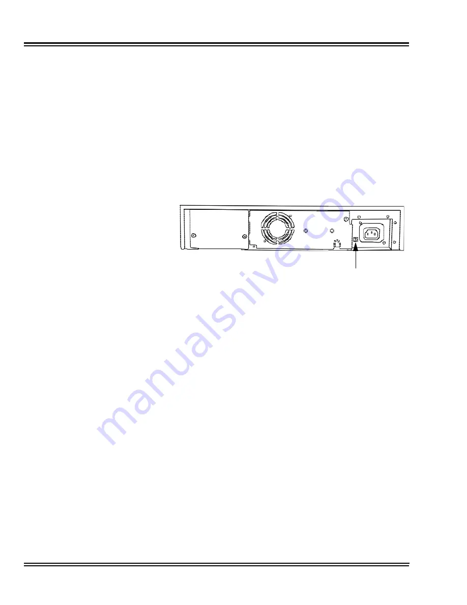
Install 19” Chassis Grounding
From the factory, the SG, ETH and PBXG grounds are located inside
the chassis and are connected to the FG ground (frame ground) on
the back of the chassis.
Each chassis (CHS2U) in the system must be grounded separately
using the procedure listed below.
1.
Ensure each Chassis is powered down and unplugged.
2.
Ground
each
chassis by connecting a 14 AWG wire from the
FG lug on the back side of the chassis to an electrical service
ground (such as a cold water pipe).
2.7.6
Install 19” Grounding on Multiple Chassis (Optional)
From the factory, the SG, ETH and PBXG grounds are located inside
the chassis and are connected to the FG ground (frame ground) on
the back of the chassis.
Each chassis (CHS2U) in the system must be grounded separately
using the procedure listed below.
1.
Ensure all Controlling and Expansion Chassis are powered
down and unplugged.
2.
Ground
each
chassis by connecting a 14 AWG wire from the
FG lug on the back side of the chassis to an electrical service
ground (such as a cold water pipe).
Figure 3-63 Chassis Grounding Lug
FG Lug
CHS2U
Summary of Contents for Univerge SV8100
Page 1: ...System Hardware Manual Issue 4 1 February 2011...
Page 2: ...THIS PAGE INTENTIONALLY LEFT BLANK...
Page 36: ...Issue 4 1 UNIVERGE SV8100 1 14 Introduction to SV8100...
Page 68: ...Issue 4 1 UNIVERGE SV8100 2 32 SV8100 System Specifications...
Page 99: ...UNIVERGE SV8100 Issue 4 1 System Hardware Manual 3 31 Figure 3 34 Install Screws Option 2...
Page 148: ...Issue 4 1 UNIVERGE SV8100 3 80 Installing the SV8100 Chassis...
Page 247: ...UNIVERGE SV8100 Issue 4 1 System Hardware Manual 4 99 Figure 4 34 Control Signal Connection...
Page 258: ...Issue 4 1 UNIVERGE SV8100 4 110 Installing the SV8100 Blades NOTES...
Page 418: ...Issue 4 1 UNIVERGE SV8100 6 64 Installing SV8100 Optional Equipment...


