UNIVERGE SV8100
Issue 4.1
System Hardware Manual
3 - 63
2.
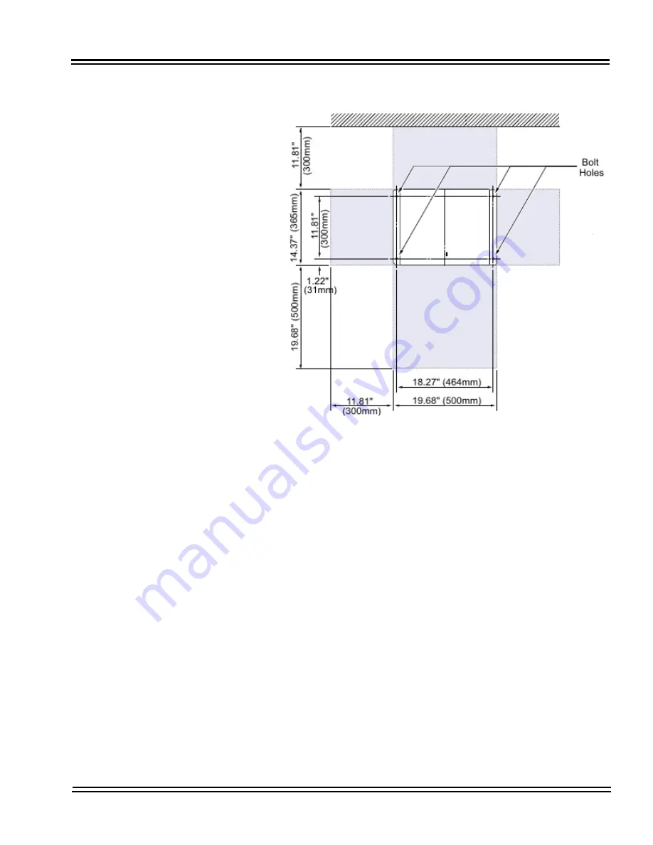
Mark and drill the four holes required for installing the CHS
BASE UNIT.
3.
Align bolt holes in CHS BASE UNIT (see
Figure 3-78 Floor
Mount Spacing Guide on page 3-63
) with holes drilled in floor
and secure using four anchor bolts.
4.
Align and install the CHS LARGE BATT BOX on top of the CHS
BASE UNIT. Refer to
Figure 3-79 Installing the CHS LARGE
BATT BOX using the CHS2U JOINT BRACKET KIT on page
3-64
.
Figure 3-78 Floor Mount Spacing Guide
Summary of Contents for Univerge SV8100
Page 1: ...System Hardware Manual Issue 4 1 February 2011...
Page 2: ...THIS PAGE INTENTIONALLY LEFT BLANK...
Page 36: ...Issue 4 1 UNIVERGE SV8100 1 14 Introduction to SV8100...
Page 68: ...Issue 4 1 UNIVERGE SV8100 2 32 SV8100 System Specifications...
Page 99: ...UNIVERGE SV8100 Issue 4 1 System Hardware Manual 3 31 Figure 3 34 Install Screws Option 2...
Page 148: ...Issue 4 1 UNIVERGE SV8100 3 80 Installing the SV8100 Chassis...
Page 247: ...UNIVERGE SV8100 Issue 4 1 System Hardware Manual 4 99 Figure 4 34 Control Signal Connection...
Page 258: ...Issue 4 1 UNIVERGE SV8100 4 110 Installing the SV8100 Blades NOTES...
Page 418: ...Issue 4 1 UNIVERGE SV8100 6 64 Installing SV8100 Optional Equipment...


