UNIVERGE SV8100
Issue 4.1
System Hardware Manual
3 - 65
3.
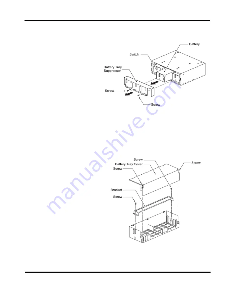
Remove two screws from front of Battery Tray Suppressor.
Refer to
Figure 3-81 Removing Battery Tray Suppressor
.
4.
Slide Battery Tray Suppressor outward to remove.
5.
Slide Battery Tray(s) out of CHS LARGE BATT BOX.
6.
Loosen two screws and remove the Battery Tray Cover. Refer
to
Figure 3-82 Removing Battery Tray Cover
.
Figure 3-81 Removing Battery Tray Suppressor
Figure 3-82 Removing Battery Tray Cover
Summary of Contents for Univerge SV8100
Page 1: ...System Hardware Manual Issue 4 1 February 2011...
Page 2: ...THIS PAGE INTENTIONALLY LEFT BLANK...
Page 36: ...Issue 4 1 UNIVERGE SV8100 1 14 Introduction to SV8100...
Page 68: ...Issue 4 1 UNIVERGE SV8100 2 32 SV8100 System Specifications...
Page 99: ...UNIVERGE SV8100 Issue 4 1 System Hardware Manual 3 31 Figure 3 34 Install Screws Option 2...
Page 148: ...Issue 4 1 UNIVERGE SV8100 3 80 Installing the SV8100 Chassis...
Page 247: ...UNIVERGE SV8100 Issue 4 1 System Hardware Manual 4 99 Figure 4 34 Control Signal Connection...
Page 258: ...Issue 4 1 UNIVERGE SV8100 4 110 Installing the SV8100 Blades NOTES...
Page 418: ...Issue 4 1 UNIVERGE SV8100 6 64 Installing SV8100 Optional Equipment...


