Issue 4.1
UNIVERGE SV8100
4 - 16
Installing the SV8100 Blades
S
ECTION
3
C
OMMON
C
ONTROL
B
LADES
The blades described in this section control the common functions of the chassis.
3.1
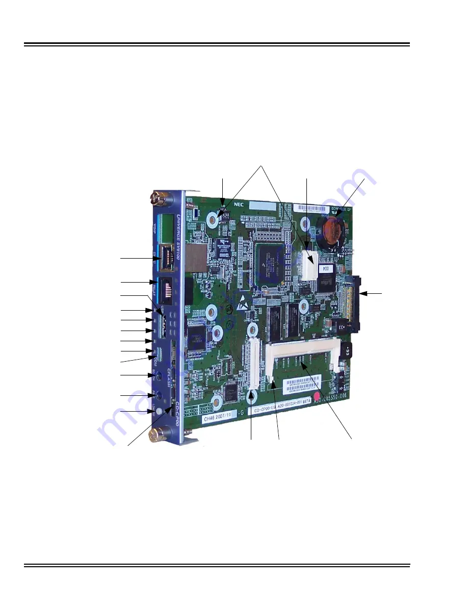
CD-CP00 (SV8100 Central Processing Unit)
Figure 4-3 CD-CP00 Blade Layout
Fast Ethernet CN7
CN6
BGM/EXSP
Control CN 10
USB CN5
Status LED1
Status LED2
Status LED3
Status LED4
Status LED5
SW6
SW1
BGM/EXSP
Control CN8
BGM/EXSP
Control CN9
CN3
Battery
CN1
CN4
CN2
Memory
PZ-32IPLA
PZ-64IPLA
PZ-128IPLA
CompactFlash
Summary of Contents for Univerge SV8100
Page 1: ...System Hardware Manual Issue 4 1 February 2011...
Page 2: ...THIS PAGE INTENTIONALLY LEFT BLANK...
Page 36: ...Issue 4 1 UNIVERGE SV8100 1 14 Introduction to SV8100...
Page 68: ...Issue 4 1 UNIVERGE SV8100 2 32 SV8100 System Specifications...
Page 99: ...UNIVERGE SV8100 Issue 4 1 System Hardware Manual 3 31 Figure 3 34 Install Screws Option 2...
Page 148: ...Issue 4 1 UNIVERGE SV8100 3 80 Installing the SV8100 Chassis...
Page 247: ...UNIVERGE SV8100 Issue 4 1 System Hardware Manual 4 99 Figure 4 34 Control Signal Connection...
Page 258: ...Issue 4 1 UNIVERGE SV8100 4 110 Installing the SV8100 Blades NOTES...
Page 418: ...Issue 4 1 UNIVERGE SV8100 6 64 Installing SV8100 Optional Equipment...


