UNIVERGE SV8100
Issue 4.1
System Hardware Manual
4 - 57
4.3.4
Connectors
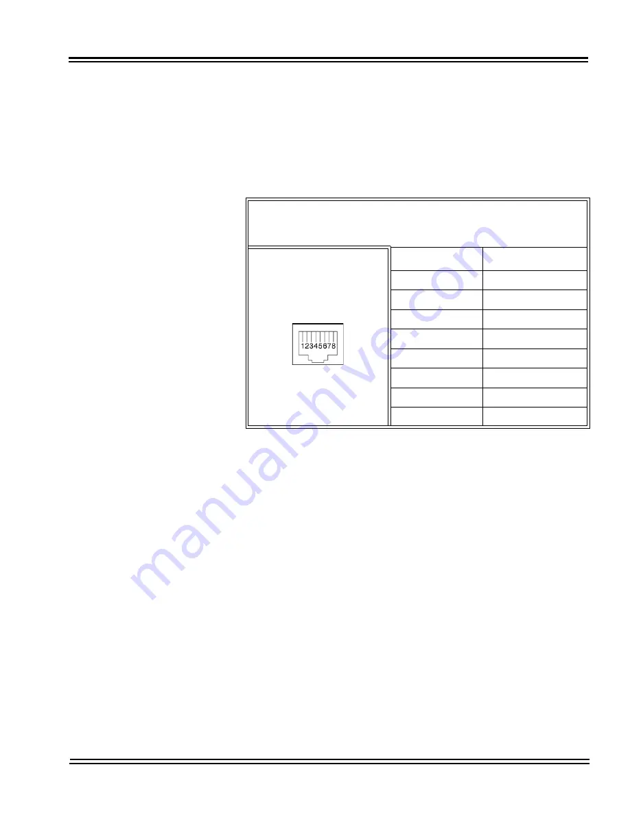
Table 4-27 CD-4LCA/CD-8LCA RJ-61 Cable Connector Pin-Outs
show the pin-outs for the RJ-61 connector. Refer to
Figure 4-19
CD-4LCA Blade on page 4-52
and
Figure 4-20 CD-8LCA Blade on
page 4-53
for illustrations showing the location of the connectors and
the pin number locations on the SLIU blades
Table 4-27 CD-4LCA/CD-8LCA RJ-61 Cable Connector Pin-Outs
RJ-61 Cable Connector
8SLIU – CN2 (ports 1~4)
8SLIU – CN2 (ports 1~4), CN3 (ports 5~8)
Pin No.
Connection
1
T4 (Tip for port 4)
2
T3 (Tip for port 3)
3
T2 (Tip for port 2)
4
R1 (Ring for port 1)
5
T1 (Tip for port 1)
6
R2 (Ring for port 2
7
R3 (Ring for port 3)
8
R4 (Ring for port 4)
Summary of Contents for Univerge SV8100
Page 1: ...System Hardware Manual Issue 4 1 February 2011...
Page 2: ...THIS PAGE INTENTIONALLY LEFT BLANK...
Page 36: ...Issue 4 1 UNIVERGE SV8100 1 14 Introduction to SV8100...
Page 68: ...Issue 4 1 UNIVERGE SV8100 2 32 SV8100 System Specifications...
Page 99: ...UNIVERGE SV8100 Issue 4 1 System Hardware Manual 3 31 Figure 3 34 Install Screws Option 2...
Page 148: ...Issue 4 1 UNIVERGE SV8100 3 80 Installing the SV8100 Chassis...
Page 247: ...UNIVERGE SV8100 Issue 4 1 System Hardware Manual 4 99 Figure 4 34 Control Signal Connection...
Page 258: ...Issue 4 1 UNIVERGE SV8100 4 110 Installing the SV8100 Blades NOTES...
Page 418: ...Issue 4 1 UNIVERGE SV8100 6 64 Installing SV8100 Optional Equipment...


