UNIVERGE SV8100
Issue 4.1
System Hardware Manual
4 - 73
5.2.2
Installation
To install the PZ-4COTE
:
1.
Four plastic spacers are included with the COIDB. Install the
plastic spacers on the CD-4COTA or CD-LTA blade. Make sure
to attach the spacers so that they extend out on the side of the
daughter board which has the CN1 connector.
2.
Position the PZ-4COTE CN1 connector over the CN4
connector on the CD-4COTA or CD-LTA. Press the blades
together, ensuring the plastic spacers lock in place.
3.
Install the PZ-4COTE blade (refer to
Figure 4-25 Installing the
PZ-4COTE Daughter Board on page 4-71
).
5.2.3
Connectors
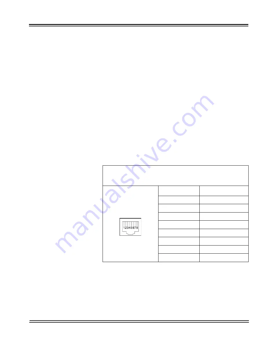
Table 4-37 PZ-4COTE RJ-61 Cable Connector Pin-Outs on page
4-73
shows the pin-outs for the RJ-61 connector. Refer to
Figure
4-25 Installing the PZ-4COTE Daughter Board on page 4-71
for an
illustration showing the location of the connectors on the PZ-4COTE
blades.
Table 4-37 PZ-4COTE RJ-61 Cable Connector Pin-Outs
RJ-61 Cable Connector
CN2, Trunks – Connecting to COIU Blade
The CN2 connector is polarity sensitive (tip-to-tip, ring-to-ring).
Pin No.
Connection
1
Circuit 8 – Tip
2
Circuit 7 – Tip
3
Circuit 6 – Tip
4
Circuit 5 – Ring
5
Circuit 5 – Tip
6
Circuit 6 – Ring
7
Circuit 7 – Ring
8
Circuit 8 – Ring
Summary of Contents for Univerge SV8100
Page 1: ...System Hardware Manual Issue 4 1 February 2011...
Page 2: ...THIS PAGE INTENTIONALLY LEFT BLANK...
Page 36: ...Issue 4 1 UNIVERGE SV8100 1 14 Introduction to SV8100...
Page 68: ...Issue 4 1 UNIVERGE SV8100 2 32 SV8100 System Specifications...
Page 99: ...UNIVERGE SV8100 Issue 4 1 System Hardware Manual 3 31 Figure 3 34 Install Screws Option 2...
Page 148: ...Issue 4 1 UNIVERGE SV8100 3 80 Installing the SV8100 Chassis...
Page 247: ...UNIVERGE SV8100 Issue 4 1 System Hardware Manual 4 99 Figure 4 34 Control Signal Connection...
Page 258: ...Issue 4 1 UNIVERGE SV8100 4 110 Installing the SV8100 Blades NOTES...
Page 418: ...Issue 4 1 UNIVERGE SV8100 6 64 Installing SV8100 Optional Equipment...


