UNIVERGE SV8100
Issue 4.1
System Hardware Manual
4 - 89
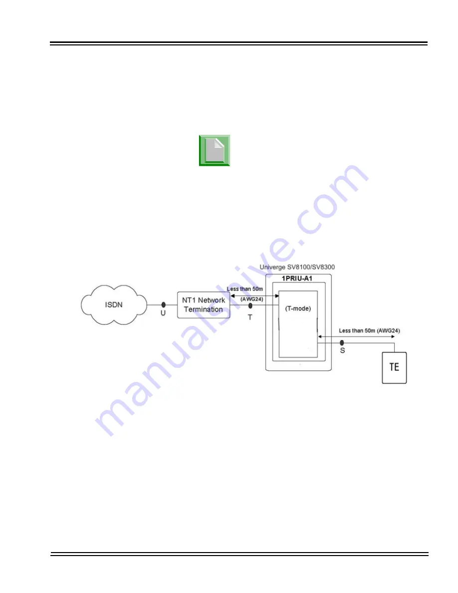
Layout for NT-1 Network on page 4-89
for a cabling diagram.)
The CSU connects to the network through
an 8-pin RJ-45/RJ48C connector. Use
either the RJ48C plug-to-RJ48C plug,
which ships with the CSU or an RJ-45/
48C plug-to RJ-45/48C plug straight
through or CAT5 cable to connect the T1
to the CSU. (Refer to
Table 4-50
CD-PRTA RJ48C Connector Pin-outs on
page 4-93
.)
With PRI Networking, a cross-over cable
must be used on the master system’s T1/
PRI blade or CSU to the telco
demarcation. If the systems are networked
side by side and not through telco, then a
straight-through cable is used.
Figure 4-30 PRI Layout for NT-1 Network
Summary of Contents for Univerge SV8100
Page 1: ...System Hardware Manual Issue 4 1 February 2011...
Page 2: ...THIS PAGE INTENTIONALLY LEFT BLANK...
Page 36: ...Issue 4 1 UNIVERGE SV8100 1 14 Introduction to SV8100...
Page 68: ...Issue 4 1 UNIVERGE SV8100 2 32 SV8100 System Specifications...
Page 99: ...UNIVERGE SV8100 Issue 4 1 System Hardware Manual 3 31 Figure 3 34 Install Screws Option 2...
Page 148: ...Issue 4 1 UNIVERGE SV8100 3 80 Installing the SV8100 Chassis...
Page 247: ...UNIVERGE SV8100 Issue 4 1 System Hardware Manual 4 99 Figure 4 34 Control Signal Connection...
Page 258: ...Issue 4 1 UNIVERGE SV8100 4 110 Installing the SV8100 Blades NOTES...
Page 418: ...Issue 4 1 UNIVERGE SV8100 6 64 Installing SV8100 Optional Equipment...


