Issue 4.1
UNIVERGE SV8100
4 - 92
Installing the SV8100 Blades
5.6.4
Connectors
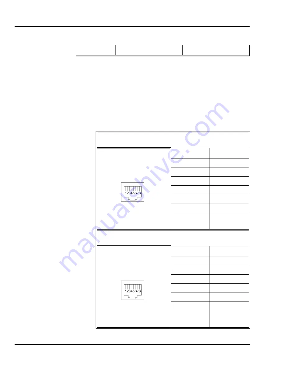
Table 4-49 CD-PRTA RJ-45 Cable Connector Pin-Outs
shows the
pin-outs for the RJ-45 connector. Refer to
Figure 4-29 CD-PRTA
Blade (Front and Side View) on page 4-87
for an illustration showing
the location of the connectors on the PRIU blade.
Note: The order of priority is set up to alarm in the order
LOS>AIS>OOF>RAI.
Table 4-49 CD-PRTA RJ-45 Cable Connector Pin-Outs
RJ-45 Cable Connector
S-Bus Connection
Pin No.
Connection
1
RB
2
RA
3
—
4
TB
5
TA
6
—
7
—
8
—
RJ-45 Cable Connector – CN2
T-Bus Connection
Pin No.
Connection
1
RA
2
RB
3
—
4
TA
5
TB
6
—
7
—
8
—
Table 4-48 ISDN LED Indications
Alarm
Details of the Alarm
LED Indication Pattern
Summary of Contents for Univerge SV8100
Page 1: ...System Hardware Manual Issue 4 1 February 2011...
Page 2: ...THIS PAGE INTENTIONALLY LEFT BLANK...
Page 36: ...Issue 4 1 UNIVERGE SV8100 1 14 Introduction to SV8100...
Page 68: ...Issue 4 1 UNIVERGE SV8100 2 32 SV8100 System Specifications...
Page 99: ...UNIVERGE SV8100 Issue 4 1 System Hardware Manual 3 31 Figure 3 34 Install Screws Option 2...
Page 148: ...Issue 4 1 UNIVERGE SV8100 3 80 Installing the SV8100 Chassis...
Page 247: ...UNIVERGE SV8100 Issue 4 1 System Hardware Manual 4 99 Figure 4 34 Control Signal Connection...
Page 258: ...Issue 4 1 UNIVERGE SV8100 4 110 Installing the SV8100 Blades NOTES...
Page 418: ...Issue 4 1 UNIVERGE SV8100 6 64 Installing SV8100 Optional Equipment...


