UNIVERGE SV8100
Issue 4.1
System Hardware Manual
6 - 3
1.
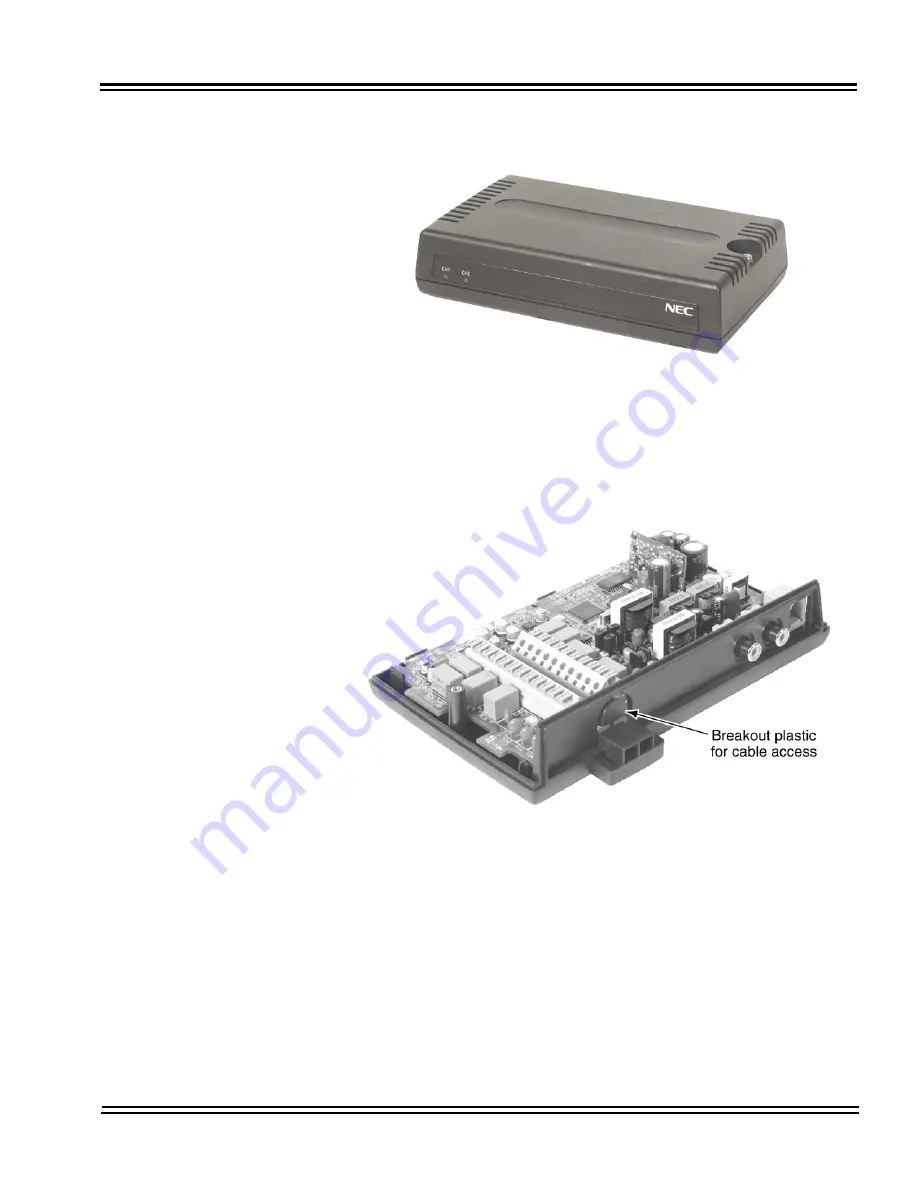
Remove the screw from the front of the PGD(2)-U10 ADP.
2.
Using a screwdriver, break out the plastic piece covering the cable hole.
3.
Set the S3 – S6 jumpers to the proper settings for the function to be used
(refer to
Table 6-2 PGD(2)-U10 ADP S3 – S6 Jumper Settings on page
6-4
).
Figure 6-2 Remove Cover from PGD(2)-U10 ADP
Figure 6-3 Remove Plastic Cover from Cable Hole
Summary of Contents for Univerge SV8100
Page 1: ...System Hardware Manual Issue 4 1 February 2011...
Page 2: ...THIS PAGE INTENTIONALLY LEFT BLANK...
Page 36: ...Issue 4 1 UNIVERGE SV8100 1 14 Introduction to SV8100...
Page 68: ...Issue 4 1 UNIVERGE SV8100 2 32 SV8100 System Specifications...
Page 99: ...UNIVERGE SV8100 Issue 4 1 System Hardware Manual 3 31 Figure 3 34 Install Screws Option 2...
Page 148: ...Issue 4 1 UNIVERGE SV8100 3 80 Installing the SV8100 Chassis...
Page 247: ...UNIVERGE SV8100 Issue 4 1 System Hardware Manual 4 99 Figure 4 34 Control Signal Connection...
Page 258: ...Issue 4 1 UNIVERGE SV8100 4 110 Installing the SV8100 Blades NOTES...
Page 418: ...Issue 4 1 UNIVERGE SV8100 6 64 Installing SV8100 Optional Equipment...


