UNIVERGE SV8100
Issue 4.1
System Hardware Manual
6 - 7
6.
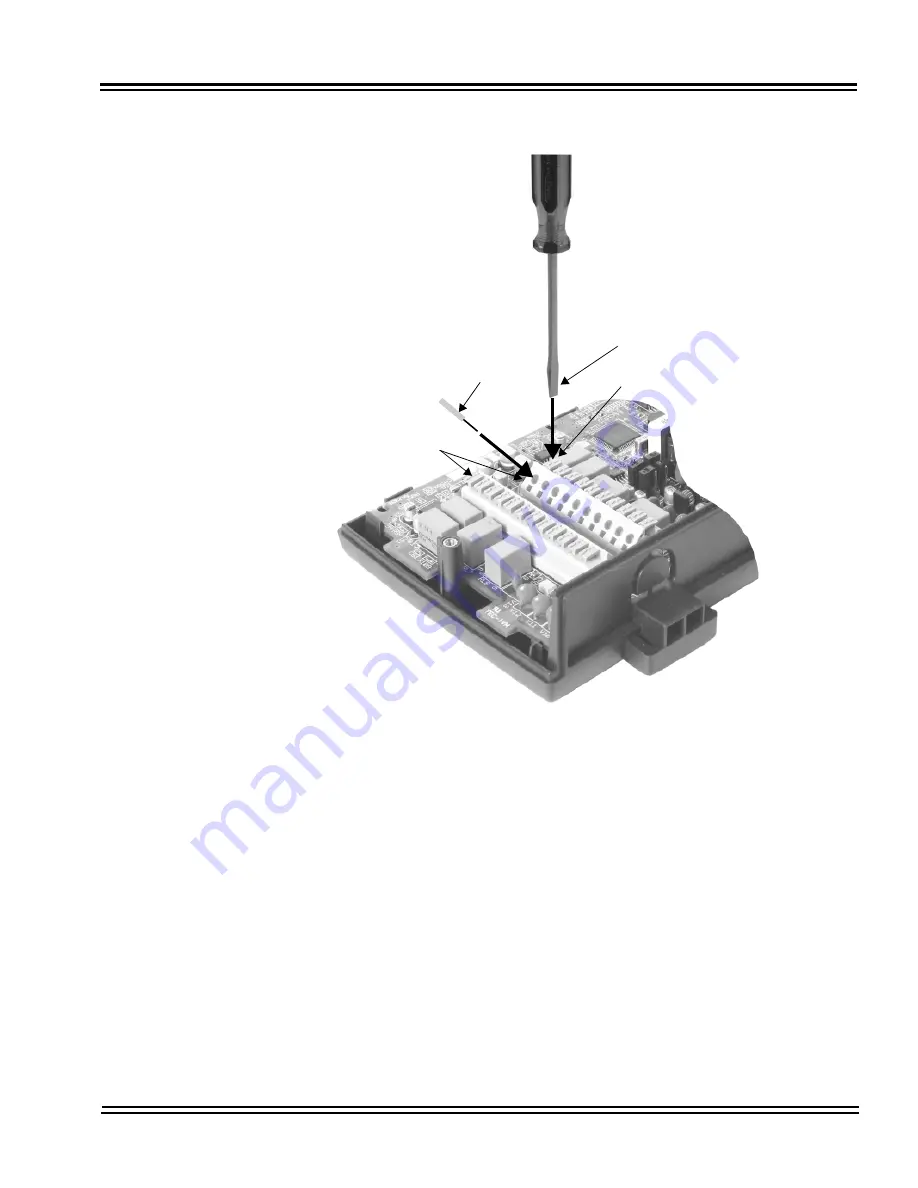
Repeat Steps 4 and 5 for any additional connections required.
7.
Replace the cover and tighten the screw to hold the cover in place.
8.
If required for the function being used, insert the RCA connectors into
the CN2 (Channel 1) and CN3 (Channel 2) connectors on the back of the
PGD(2)-U10 ADP.
Figure 6-6 Connecting Cable to the PGD(2)-U10 ADP
Flat-head screwdriver
Press down
Cable
CN4, CN5
Summary of Contents for Univerge SV8100
Page 1: ...System Hardware Manual Issue 4 1 February 2011...
Page 2: ...THIS PAGE INTENTIONALLY LEFT BLANK...
Page 36: ...Issue 4 1 UNIVERGE SV8100 1 14 Introduction to SV8100...
Page 68: ...Issue 4 1 UNIVERGE SV8100 2 32 SV8100 System Specifications...
Page 99: ...UNIVERGE SV8100 Issue 4 1 System Hardware Manual 3 31 Figure 3 34 Install Screws Option 2...
Page 148: ...Issue 4 1 UNIVERGE SV8100 3 80 Installing the SV8100 Chassis...
Page 247: ...UNIVERGE SV8100 Issue 4 1 System Hardware Manual 4 99 Figure 4 34 Control Signal Connection...
Page 258: ...Issue 4 1 UNIVERGE SV8100 4 110 Installing the SV8100 Blades NOTES...
Page 418: ...Issue 4 1 UNIVERGE SV8100 6 64 Installing SV8100 Optional Equipment...


