Issue 4.1
UNIVERGE SV8100
6 - 16
Installing SV8100 Optional Equipment
4.
Terminate the extension leads to GRN/RED of the modular jack.
Terminate the unused leads to the jack.
5.
Install bridging clips as required.
6.
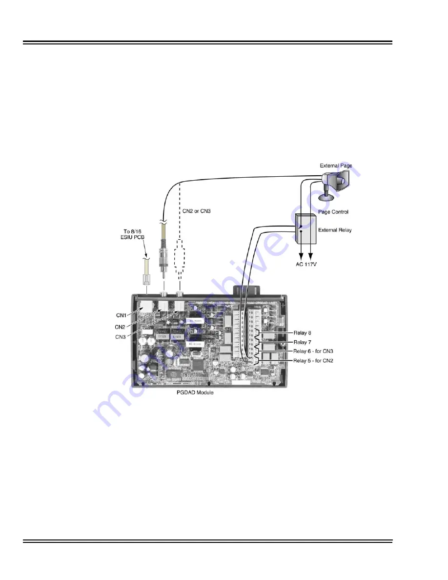
Plug a modular line cord from the mod jack to the CN1 connector on the
PGD(2)-U10 ADP.
7.
Connect the two-conductor station cable from the CN5 connectors within
the PGD(2)-U10 ADP to the external relay/external page.
Figure 6-13 PGD(2)-U10 ADP Cable Connection
Summary of Contents for Univerge SV8100
Page 1: ...System Hardware Manual Issue 4 1 February 2011...
Page 2: ...THIS PAGE INTENTIONALLY LEFT BLANK...
Page 36: ...Issue 4 1 UNIVERGE SV8100 1 14 Introduction to SV8100...
Page 68: ...Issue 4 1 UNIVERGE SV8100 2 32 SV8100 System Specifications...
Page 99: ...UNIVERGE SV8100 Issue 4 1 System Hardware Manual 3 31 Figure 3 34 Install Screws Option 2...
Page 148: ...Issue 4 1 UNIVERGE SV8100 3 80 Installing the SV8100 Chassis...
Page 247: ...UNIVERGE SV8100 Issue 4 1 System Hardware Manual 4 99 Figure 4 34 Control Signal Connection...
Page 258: ...Issue 4 1 UNIVERGE SV8100 4 110 Installing the SV8100 Blades NOTES...
Page 418: ...Issue 4 1 UNIVERGE SV8100 6 64 Installing SV8100 Optional Equipment...


