Issue 4.1
UNIVERGE SV8100
6 - 34
Installing SV8100 Optional Equipment
11.3.1
ADA-L UNIT Switch Settings
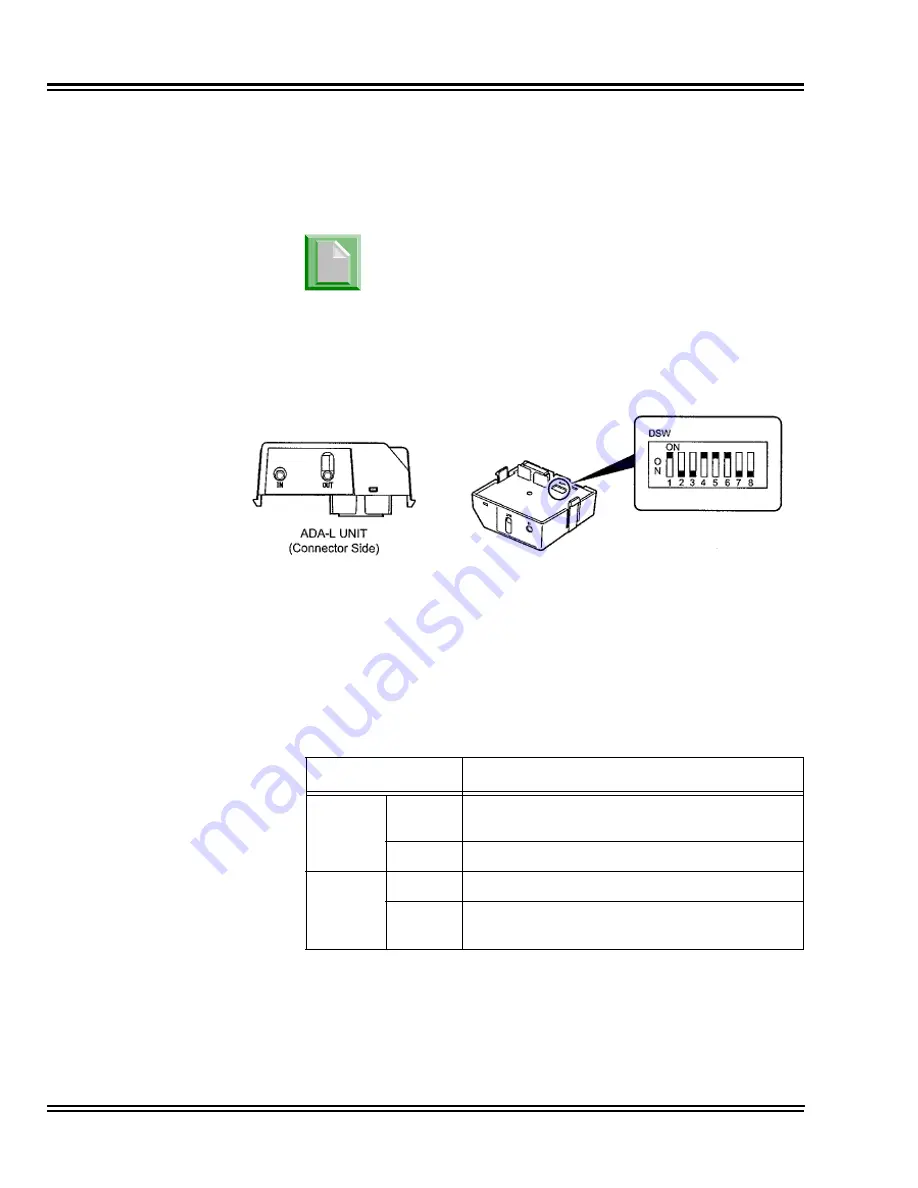
Figure 6-23 ADA-L UNIT
shows the location of the switches. The dip
switches (DSW) allow a technician to configure the unit for specific
settings.
To provide control to the recorder or to enable/disable the record start warning
tones, refer to
Table 6-3 ADA-L Unit Switch Settings
.
Figure 6-23 ADA-L UNIT
Table 6-3 ADA-L Unit Switch Settings
Switch
Description/Settings
SW1
SW1-1
Connects to Multiline Terminal
Connect = Default
SW1-2
Not Used
SW2
SW2-1
Sets External Equipment Impedance to 600
Ω
SW2-2
Used for Complex Impedance Devices
(< 30
Ω
Input Impedance)
Due to location, set switches prior to installation of
ADA-L on DTL/ITL multiline terminal.
Summary of Contents for Univerge SV8100
Page 1: ...System Hardware Manual Issue 4 1 February 2011...
Page 2: ...THIS PAGE INTENTIONALLY LEFT BLANK...
Page 36: ...Issue 4 1 UNIVERGE SV8100 1 14 Introduction to SV8100...
Page 68: ...Issue 4 1 UNIVERGE SV8100 2 32 SV8100 System Specifications...
Page 99: ...UNIVERGE SV8100 Issue 4 1 System Hardware Manual 3 31 Figure 3 34 Install Screws Option 2...
Page 148: ...Issue 4 1 UNIVERGE SV8100 3 80 Installing the SV8100 Chassis...
Page 247: ...UNIVERGE SV8100 Issue 4 1 System Hardware Manual 4 99 Figure 4 34 Control Signal Connection...
Page 258: ...Issue 4 1 UNIVERGE SV8100 4 110 Installing the SV8100 Blades NOTES...
Page 418: ...Issue 4 1 UNIVERGE SV8100 6 64 Installing SV8100 Optional Equipment...


