Issue 4.1
UNIVERGE SV8100
6 - 36
Installing SV8100 Optional Equipment
4.
Push the two stopper tabs through the slots to separate the tilt
leg from the leg support.
5.
Lay the tilt leg and the leg support flat to expose ADA-L UNIT
compartment.
6.
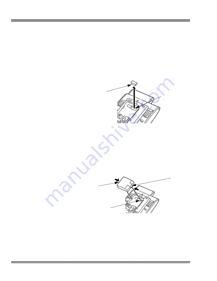
Carefully pry loose the knockout covering the bottom option
interface (refer to
Figure 6-25 Bottom Option Interface
Knockout
).
7.
Using the exposed Bottom Option Interface as a guide, install
the ADA-L UNIT in the bottom of the DTL/ITL multiline terminal.
Push down until left and right tabs are seated (Refer to
Figure
6-26 Install ADA-L UNIT
).
8.
Return tilt leg to original position.
9.
Reconnect all cables previously disconnected.
Figure 6-25 Bottom Option Interface Knockout
Figure 6-26 Install ADA-L UNIT
Knockout
Bottom Option
Interface
Bottom Option
Interface
Tab
Tab
Summary of Contents for Univerge SV8100
Page 1: ...System Hardware Manual Issue 4 1 February 2011...
Page 2: ...THIS PAGE INTENTIONALLY LEFT BLANK...
Page 36: ...Issue 4 1 UNIVERGE SV8100 1 14 Introduction to SV8100...
Page 68: ...Issue 4 1 UNIVERGE SV8100 2 32 SV8100 System Specifications...
Page 99: ...UNIVERGE SV8100 Issue 4 1 System Hardware Manual 3 31 Figure 3 34 Install Screws Option 2...
Page 148: ...Issue 4 1 UNIVERGE SV8100 3 80 Installing the SV8100 Chassis...
Page 247: ...UNIVERGE SV8100 Issue 4 1 System Hardware Manual 4 99 Figure 4 34 Control Signal Connection...
Page 258: ...Issue 4 1 UNIVERGE SV8100 4 110 Installing the SV8100 Blades NOTES...
Page 418: ...Issue 4 1 UNIVERGE SV8100 6 64 Installing SV8100 Optional Equipment...


