UNIVERGE SV8100
Issue 4.1
System Hardware Manual
6 - 47
10.
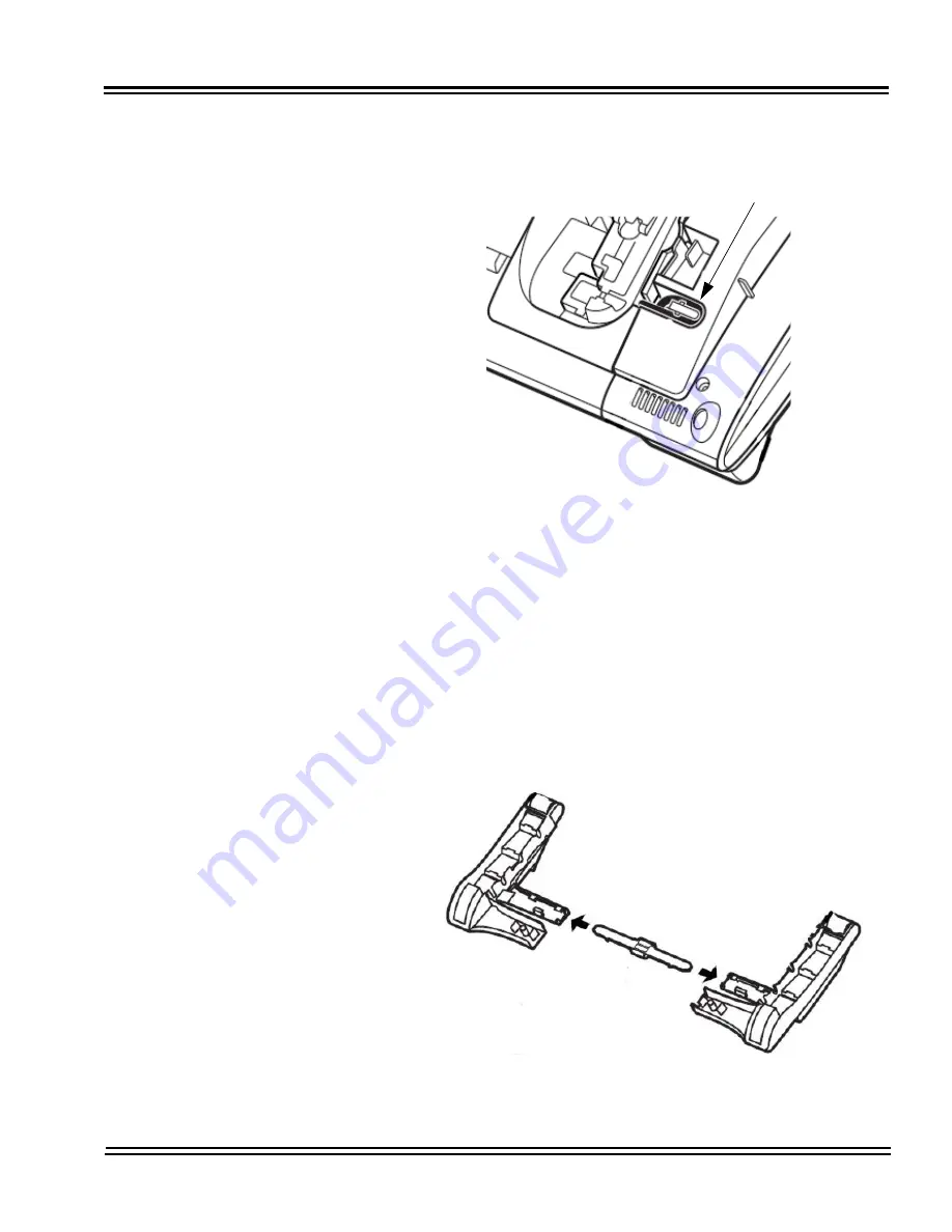
Gently press the serial cable into the grooved cutout for the
cable.
11.
Connect the serial connection cord (refer to
Figure 6-39 Attach
PSA-L Unit to the Multiline Terminal on page 6-46
) from the
PSA-L UNIT to the terminal body.
12.
Open the Dip Switch Cover (refer to
Figure 6-35 PSA-L UNIT
Connections on page 6-44
). Set the dip switch on the PSA-L
adapter to the required position. Close the cover.
13.
If using the handset, place the stopper in the tilt leg.
Figure 6-40 Grooved Cutout for Serial Cable
Figure 6-41 Insert Stopper for Handset Use
Cable Groove
Summary of Contents for Univerge SV8100
Page 1: ...System Hardware Manual Issue 4 1 February 2011...
Page 2: ...THIS PAGE INTENTIONALLY LEFT BLANK...
Page 36: ...Issue 4 1 UNIVERGE SV8100 1 14 Introduction to SV8100...
Page 68: ...Issue 4 1 UNIVERGE SV8100 2 32 SV8100 System Specifications...
Page 99: ...UNIVERGE SV8100 Issue 4 1 System Hardware Manual 3 31 Figure 3 34 Install Screws Option 2...
Page 148: ...Issue 4 1 UNIVERGE SV8100 3 80 Installing the SV8100 Chassis...
Page 247: ...UNIVERGE SV8100 Issue 4 1 System Hardware Manual 4 99 Figure 4 34 Control Signal Connection...
Page 258: ...Issue 4 1 UNIVERGE SV8100 4 110 Installing the SV8100 Blades NOTES...
Page 418: ...Issue 4 1 UNIVERGE SV8100 6 64 Installing SV8100 Optional Equipment...


