Issue 4.1
UNIVERGE SV8100
6 - 60
Installing SV8100 Optional Equipment
11.6.2
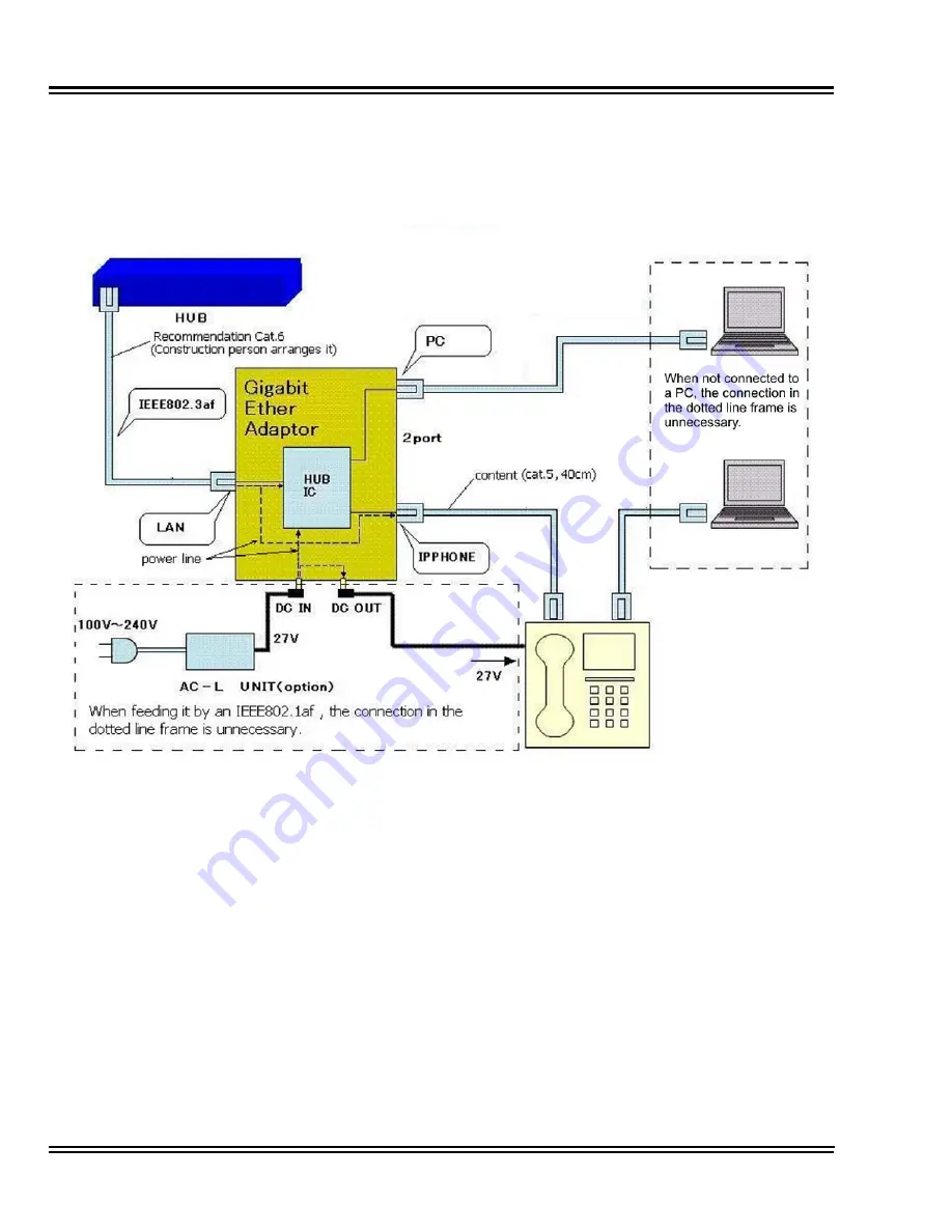
GBA-L UNIT Connection
The following chart outlines the connectivity available to the GBA-L
UNIT:
11.6.3
LED Display
The following provides a list of each LED and associated operation
and status indications. Refer to
Figure 6-63 GBA-L UNIT LED
Display on page 6-61
for the location of the LEDs on the GBA-L
UNIT.
Figure 6-62 GBA-L UNIT Connectivity Chart
Summary of Contents for Univerge SV8100
Page 1: ...System Hardware Manual Issue 4 1 February 2011...
Page 2: ...THIS PAGE INTENTIONALLY LEFT BLANK...
Page 36: ...Issue 4 1 UNIVERGE SV8100 1 14 Introduction to SV8100...
Page 68: ...Issue 4 1 UNIVERGE SV8100 2 32 SV8100 System Specifications...
Page 99: ...UNIVERGE SV8100 Issue 4 1 System Hardware Manual 3 31 Figure 3 34 Install Screws Option 2...
Page 148: ...Issue 4 1 UNIVERGE SV8100 3 80 Installing the SV8100 Chassis...
Page 247: ...UNIVERGE SV8100 Issue 4 1 System Hardware Manual 4 99 Figure 4 34 Control Signal Connection...
Page 258: ...Issue 4 1 UNIVERGE SV8100 4 110 Installing the SV8100 Blades NOTES...
Page 418: ...Issue 4 1 UNIVERGE SV8100 6 64 Installing SV8100 Optional Equipment...


