UNIVERGE SV8100
Issue 4.1
System Hardware Manual
6 - 61
S
ECTION
12
P
OWER
F
AILURE
T
ELEPHONES
12.1
Power Failure
The system allows connection for basic telephone service during a power
failure. The power failure operation occurs during a commercial power failure,
and is not affected by blade failure. Power Failure Transfer is provided by
connecting to the CD-4COTA blade.
The CD-4COTA Blade provides 2 Power Failure Transfer circuits.
The CN3 and CN5 connectors each provide connection to four analog trunk
ports,
which are polarity sensitive (tip to tip, ring to ring)
. The power
failure circuits, however, are not polarity sensitive. A maximum of 15
CD-4COTA blades per system is allowed.
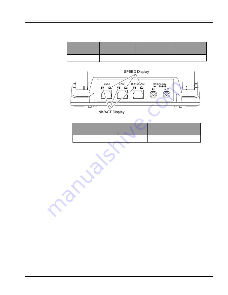
Figure 6-63 GBA-L UNIT LED Display
LED Name
When 1000Mbps is
Connected
When 100Mbps is
Connected
When 10Mbps is
Connected
SPEED Display
Green Lighting
Red Lighting
Turning Off
LED Name
At LINK
ACT
(At the Data Communication)
LINK/ACT Display
Green Lighting
Green Blinking
Summary of Contents for Univerge SV8100
Page 1: ...System Hardware Manual Issue 4 1 February 2011...
Page 2: ...THIS PAGE INTENTIONALLY LEFT BLANK...
Page 36: ...Issue 4 1 UNIVERGE SV8100 1 14 Introduction to SV8100...
Page 68: ...Issue 4 1 UNIVERGE SV8100 2 32 SV8100 System Specifications...
Page 99: ...UNIVERGE SV8100 Issue 4 1 System Hardware Manual 3 31 Figure 3 34 Install Screws Option 2...
Page 148: ...Issue 4 1 UNIVERGE SV8100 3 80 Installing the SV8100 Chassis...
Page 247: ...UNIVERGE SV8100 Issue 4 1 System Hardware Manual 4 99 Figure 4 34 Control Signal Connection...
Page 258: ...Issue 4 1 UNIVERGE SV8100 4 110 Installing the SV8100 Blades NOTES...
Page 418: ...Issue 4 1 UNIVERGE SV8100 6 64 Installing SV8100 Optional Equipment...


