UNIVERGE SV8100
Issue 4.1
System Hardware Manual
3 - 13
.
4.
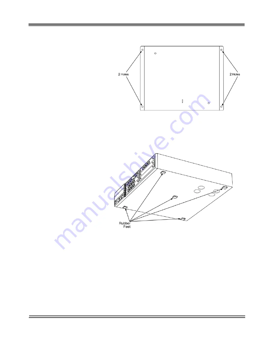
Install the five rubber feet to the bottom of the chassis.
5.
Position the chassis on top of the CHS BASE UNIT.
6.
Secure the chassis to the CHS BASE UNIT using eight screws
supplied with the CHS2U JOINT BRACKET KIT.
Figure 3-13 Secure CHS BASE UNIT with Anchor Bolts
Figure 3-14 Install Rubber Feet
Summary of Contents for Univerge SV8100
Page 1: ...System Hardware Manual Issue 4 1 February 2011...
Page 2: ...THIS PAGE INTENTIONALLY LEFT BLANK...
Page 36: ...Issue 4 1 UNIVERGE SV8100 1 14 Introduction to SV8100...
Page 68: ...Issue 4 1 UNIVERGE SV8100 2 32 SV8100 System Specifications...
Page 99: ...UNIVERGE SV8100 Issue 4 1 System Hardware Manual 3 31 Figure 3 34 Install Screws Option 2...
Page 148: ...Issue 4 1 UNIVERGE SV8100 3 80 Installing the SV8100 Chassis...
Page 247: ...UNIVERGE SV8100 Issue 4 1 System Hardware Manual 4 99 Figure 4 34 Control Signal Connection...
Page 258: ...Issue 4 1 UNIVERGE SV8100 4 110 Installing the SV8100 Blades NOTES...
Page 418: ...Issue 4 1 UNIVERGE SV8100 6 64 Installing SV8100 Optional Equipment...


