Issue 4.1
UNIVERGE SV8100
3 - 14
Installing the SV8100 Chassis
7.
Connect the ground wire to all chassis. Refer to
2.7.5 Install
19” Chassis Grounding on page 3-52
for complete details on
grounding the system.
8.
Refer to
2.7 Installing the 19” Chassis on page 3-39
to continue
installation of the chassis or, Chapter 5 paragraph
2.2
Installing an Extension or Trunk Blade on page 4-4
for
installation of blades.
2.2.2
Multiple CHS2U Chassis Installation
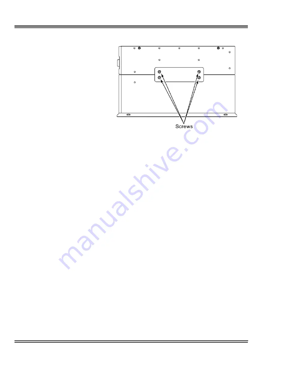
Expansion chassis can be secured to the CHS BASE UNIT and will
require an additional CHS2U JOINT BRACKET KIT per chassis.
Figure 3-15 Install CHS2U JOINT BRACKET KIT
Summary of Contents for Univerge SV8100
Page 1: ...System Hardware Manual Issue 4 1 February 2011...
Page 2: ...THIS PAGE INTENTIONALLY LEFT BLANK...
Page 36: ...Issue 4 1 UNIVERGE SV8100 1 14 Introduction to SV8100...
Page 68: ...Issue 4 1 UNIVERGE SV8100 2 32 SV8100 System Specifications...
Page 99: ...UNIVERGE SV8100 Issue 4 1 System Hardware Manual 3 31 Figure 3 34 Install Screws Option 2...
Page 148: ...Issue 4 1 UNIVERGE SV8100 3 80 Installing the SV8100 Chassis...
Page 247: ...UNIVERGE SV8100 Issue 4 1 System Hardware Manual 4 99 Figure 4 34 Control Signal Connection...
Page 258: ...Issue 4 1 UNIVERGE SV8100 4 110 Installing the SV8100 Blades NOTES...
Page 418: ...Issue 4 1 UNIVERGE SV8100 6 64 Installing SV8100 Optional Equipment...


