1048
Appendix B
Revision History
User’s Manual U16580EE3V1UD00
EE2
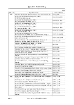
Figure 6-14 “Initialization of DMA Transfer for Serial Data Reception” added 6.4.3 (1), p.197
Figure 6-15 “Operation of DMA Channel 4/5”, added
6.4.3 (1), p.198
Figure 6-16 “DMA Channel 4 and 5 Trigger Signal Timing” added
6.4.3 (1), p.199
Table 6-3 “DMA Configuration of Serial Data Transmission”,
DMA trigger factor changed
6.4.3 (2), p. 200
Figure 6-17 “Initialization of DMA Transfer for Serial Data Transmission”
added
6.4.3 (2), p. 201
Figure 6-18 “DMA Channel 6 and 7 Trigger Signal Timing”, added
6.4.3 (2), p.202
Figure 6-19 “Operation of DMA Channel 6/7” added
6.4.3 (2), p.203
Figure 6-20 “CPU and DMA Controller Processing of DMA Transfer Termi-
nation (Example)” added
6.4.4, p.204
Table 6-4 “Relations Between DMA Trigger Factors and DMA Completion
Interrupts”, DMA trigger factor changed
6.5, p. 205
Figure 6-21 “Correlation between Serial I/O Interface Interrupts and DMA
Completion Interrupts” added
6.5, p.206
Figure 7-10 “Interrupt Control Register (PICn)”,
value after reset and Man bit description changed
7.3.4, p.224
Figure 7-13 “Interrupt Service Priority Register (ISPR)”, R/W changed to R 7.3.6, p.230
Figure 7-15 “Interrupt Mode Register 0 (INTM0)”,
description of bits ESN1 and ESN0 added
7.3.8 (1), p.233
Figure 9-10 “TMPn Option Register 0 (TPnOPT0)”,
description of TPnOVF flag changed
9.4 (6), p.258
Figure 9-27 “Basic Operation Timing in PWM Mode”, remark 2 changed
9.5.6, p.283, 284
10.3 (7) “TMRn I/O control register 4 (TRnIOC4)”, description changed
10.3 (7), p.318
Figure 10-19 “TMRn Option Register 0 (TRnOPT0)” changed
10.3 (8), p.320
10.3 (11) “TMRn option register 3 (TRnOPT3)” Caution changed
10.3(11), p.325
Figure 10-35 “A/D Conversion Trigger Output Controller”, changed
10.8, p.362
Figure 10-56 “High-Accuracy T-PWM Mode Block Diagram”, changed
10.10.9 (1), p.405
10.10.9 (2) (d) “Interrupts” changed, Notes added
10.10.9 (2) (d), p.406
10.10.9 (7) “Caution on timer output in high-accuracy T-PWM mode”,
changed
10.10.9 (7), p.414-416
Table 10-1 “Positive Phase Operation Condition List” changed
10.10.9 (8), p.417
Table 10-2 “Negative Phase Operation Condition List” changed
10.10.9 (8), p.417
10.10.9 (8) “Timer output change after compare register updating”, added
10.10.9 (8), p.417-429
10.10.9 (9) “Dead time control in high-accuracy T-PWM mode”, changed
10.10.9 (9), p.430
10.10.9 (10) “Cautions on dead time control in high-accuracy T-PWM
mode”, added
10.10.9 (10), p.431
10.10.9 (11) “Caution on rewriting cycles in high-accuracy T-PWM mode”,
changed
10.10.9 (11), p.432
10.10.9 (12) “Error interrupt (INTTRnER) in high-accuracy T-PWM mode”,
changed
10.10.9 (12), p.433
Figure 10-72 “Block Diagram in PWM Mode With Dead Time”, changed
10.10.10 (1), p.434
10.10.10 (3) (e) “Reload thinning out function setting”, changed
10.10.10 (3) (e), p.437
Table 11-3 “Capture/Compare Functions in Each Mode” changed
11.3 (1), p.447
Table 11-4 “Capture/Compare Functions in Each Mode” changed
11.3 (2), p.449
(2/5)
Edition No.
Major items revised
Revised Sections
Summary of Contents for V850E/PH2
Page 6: ...6 Preface User s Manual U16580EE3V1UD00...
Page 16: ...16 User s Manual U16580EE3V1UD00...
Page 28: ...28 User s Manual U16580EE3V1UD00...
Page 32: ...32 User s Manual U16580EE3V1UD00...
Page 84: ...84 Chapter 2 Pin Functions User s Manual U16580EE3V1UD00 MEMO...
Page 144: ...144 Chapter 3 CPU Functions User s Manual U16580EE3V1UD00 MEMO...
Page 192: ...192 Chapter 5 Memory Access Control Function PD70F3187 only User s Manual U16580EE3V1UD00 MEMO...
Page 312: ...312 Chapter 9 16 Bit Timer Event Counter P User s Manual U16580EE3V1UD00 MEMO...
Page 534: ...534 Chapter 11 16 bit Timer Event Counter T User s Manual U16580EE3V1UD00...
Page 969: ...969 Chapter 20 Port Functions User s Manual U16580EE3V1UD00 MEMO...
Page 970: ...970 Chapter 20 Port Functions User s Manual U16580EE3V1UD00...
Page 976: ...976 Chapter 22 Internal RAM Parity Check Function User s Manual U16580EE3V1UD00 MEMO...
Page 984: ...984 Chapter 23 On Chip Debug Function OCD User s Manual U16580EE3V1UD00 MEMO...
Page 1006: ...1006 Chapter 24 Flash Memory User s Manual U16580EE3V1UD00 MEMO...
Page 1036: ...1036 Chapter 27 Recommended Soldering Conditions User s Manual U16580EE3V1UD00 MEMO...
Page 1046: ...1046 Appendix A Index User s Manual U16580EE3V1UD00 MEMO...
Page 1052: ...1052 User s Manual U16580EE3V1UD00...
Page 1053: ......


