749
Chapter 18
AFCAN Controller
User’s Manual U16580EE3V1UD00
(h) Interframe space
The interframe space is inserted after a data frame, remote frame, error frame, or overload frame
to separate one frame from the next.
•
The bus state differs depending on the error status.
– Error active node
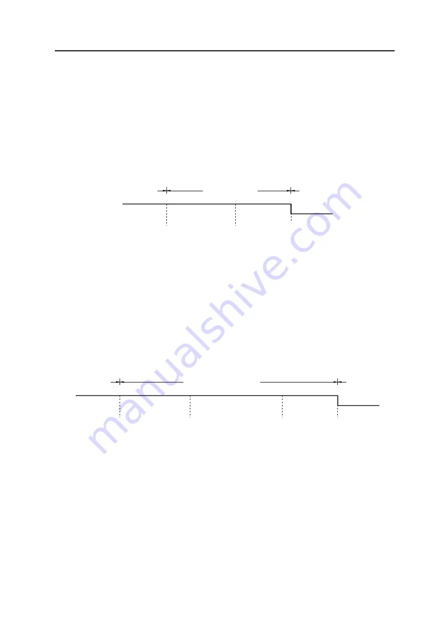
The interframe space consists of a 3-bit intermission field and a bus idle field.
Figure 18-13:
Interframe space (error active node)
Notes: 1.
Bus idle: State in which the bus is not used by any node.
2.
D: Dominant = 0
R: Recessive = 1
– Error passive node
The interframe space consists of an intermission field, a suspend transmission field, and a bus idle
field.
Figure 18-14:
Interframe space (error passive node)
Notes: 1.
Bus idle:
State in which the bus is not used by any node.
Suspend transmission:
Sequence of 8 recessive-level bits transmitted
from the node in the error passive status.
2.
D: Dominant = 0
R: Recessive = 1
Usually, the intermission field is 3 bits. If the transmitting node detects a dominant level at the third
bit of the intermission field, however, it executes transmission.
R
D
Interframe space
Intermission
(3 bits)
Bus idle
(0 to
∞
bits)
(Frame)
(Frame)
R
D
Interframe space
Intermission
(3 bits)
Suspend transmission
(8 bits)
Bus idle
(0 to
∞
bits)
(Frame)
(Frame)
Summary of Contents for V850E/PH2
Page 6: ...6 Preface User s Manual U16580EE3V1UD00...
Page 16: ...16 User s Manual U16580EE3V1UD00...
Page 28: ...28 User s Manual U16580EE3V1UD00...
Page 32: ...32 User s Manual U16580EE3V1UD00...
Page 84: ...84 Chapter 2 Pin Functions User s Manual U16580EE3V1UD00 MEMO...
Page 144: ...144 Chapter 3 CPU Functions User s Manual U16580EE3V1UD00 MEMO...
Page 192: ...192 Chapter 5 Memory Access Control Function PD70F3187 only User s Manual U16580EE3V1UD00 MEMO...
Page 312: ...312 Chapter 9 16 Bit Timer Event Counter P User s Manual U16580EE3V1UD00 MEMO...
Page 534: ...534 Chapter 11 16 bit Timer Event Counter T User s Manual U16580EE3V1UD00...
Page 969: ...969 Chapter 20 Port Functions User s Manual U16580EE3V1UD00 MEMO...
Page 970: ...970 Chapter 20 Port Functions User s Manual U16580EE3V1UD00...
Page 976: ...976 Chapter 22 Internal RAM Parity Check Function User s Manual U16580EE3V1UD00 MEMO...
Page 984: ...984 Chapter 23 On Chip Debug Function OCD User s Manual U16580EE3V1UD00 MEMO...
Page 1006: ...1006 Chapter 24 Flash Memory User s Manual U16580EE3V1UD00 MEMO...
Page 1036: ...1036 Chapter 27 Recommended Soldering Conditions User s Manual U16580EE3V1UD00 MEMO...
Page 1046: ...1046 Appendix A Index User s Manual U16580EE3V1UD00 MEMO...
Page 1052: ...1052 User s Manual U16580EE3V1UD00...
Page 1053: ......


