828
Chapter 18
AFCAN Controller
User’s Manual U16580EE3V1UD00
18.13 Diagnosis Functions and Special Operational Modes
The CAN module provides a receive-only mode, single-shot mode, and self-test mode to support CAN
bus diagnosis functions or the operation of special CAN communication methods.
18.13.1 Receive-only
mode
The receive-only mode is used to monitor receive messages without causing any interference on the
CAN bus and can be used for CAN bus analysis nodes.
For example, this mode can be used for automatic baud-rate detection. The baud rate in the CAN mod-
ule is changed until “valid reception” is detected, so that the baud rates in the module match (“valid
reception” means a message frame has been received in the CAN protocol layer without occurrence of
an error and with an appropriate ACK between nodes connected to the CAN bus). A valid reception
does not require message frames to be stored in a receive message buffer (data frames) or transmit
message buffer (remote frames). The event of valid reception is indicated by setting the VALID bit of the
CnCTRL register (1).
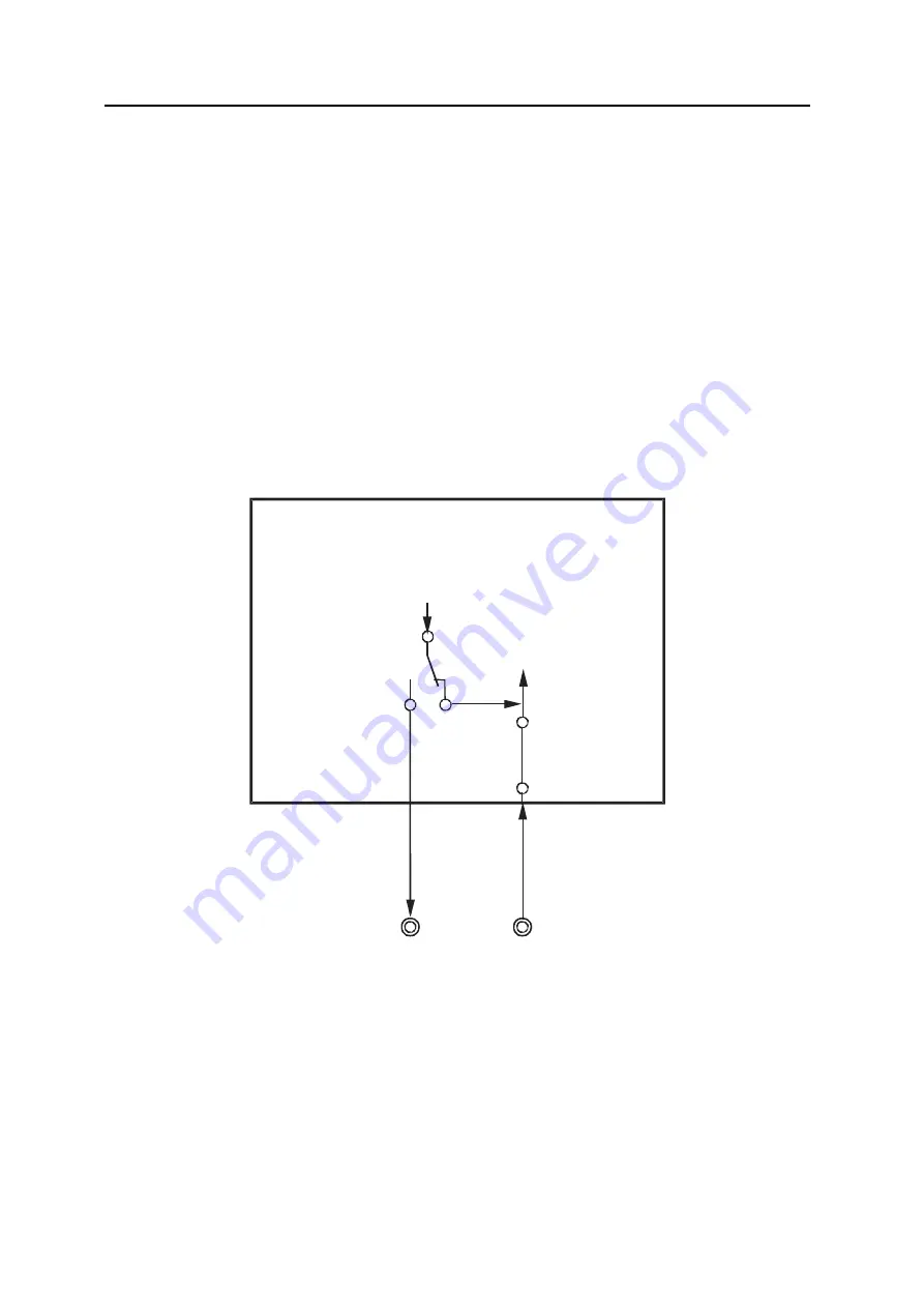
Figure 18-32:
CAN module terminal connection in receive-only mode
In the receive-only mode, no message frames can be transmitted from the CAN module to the CAN
bus. Transmit requests issued for message buffers defined as transmit message buffers are held pend-
ing.
In the receive-only mode, the CAN transmission pin (CTXDn) in the CAN module is fixed to the reces-
sive level. Therefore, no active error flag can be transmitted from the CAN module to the CAN bus even
when a CAN bus error is detected while receiving a message frame. Since no transmission can be
issued from the CAN module, the transmission error counter the CnERC.TEC7 to CnERC.TEC0 bits
are never updated. Therefore, a CAN module in the receive-only mode does not enter the bus-off state.
Furthermore, in the receive-only mode ACK is not returned to the CAN bus in this mode upon the valid
reception of a message frame. Internally, the local node recognizes that it has transmitted ACK. An
overload frame cannot be transmitted to the CAN bus.
Caution
If only two CAN nodes are connected to the CAN bus and one of them is
CAN macro
Rx
Tx
CTXDn
CRXDn
Fixed to
the recessive
level
Summary of Contents for V850E/PH2
Page 6: ...6 Preface User s Manual U16580EE3V1UD00...
Page 16: ...16 User s Manual U16580EE3V1UD00...
Page 28: ...28 User s Manual U16580EE3V1UD00...
Page 32: ...32 User s Manual U16580EE3V1UD00...
Page 84: ...84 Chapter 2 Pin Functions User s Manual U16580EE3V1UD00 MEMO...
Page 144: ...144 Chapter 3 CPU Functions User s Manual U16580EE3V1UD00 MEMO...
Page 192: ...192 Chapter 5 Memory Access Control Function PD70F3187 only User s Manual U16580EE3V1UD00 MEMO...
Page 312: ...312 Chapter 9 16 Bit Timer Event Counter P User s Manual U16580EE3V1UD00 MEMO...
Page 534: ...534 Chapter 11 16 bit Timer Event Counter T User s Manual U16580EE3V1UD00...
Page 969: ...969 Chapter 20 Port Functions User s Manual U16580EE3V1UD00 MEMO...
Page 970: ...970 Chapter 20 Port Functions User s Manual U16580EE3V1UD00...
Page 976: ...976 Chapter 22 Internal RAM Parity Check Function User s Manual U16580EE3V1UD00 MEMO...
Page 984: ...984 Chapter 23 On Chip Debug Function OCD User s Manual U16580EE3V1UD00 MEMO...
Page 1006: ...1006 Chapter 24 Flash Memory User s Manual U16580EE3V1UD00 MEMO...
Page 1036: ...1036 Chapter 27 Recommended Soldering Conditions User s Manual U16580EE3V1UD00 MEMO...
Page 1046: ...1046 Appendix A Index User s Manual U16580EE3V1UD00 MEMO...
Page 1052: ...1052 User s Manual U16580EE3V1UD00...
Page 1053: ......


