background image

Setup and Operation      2-13

Status Bar

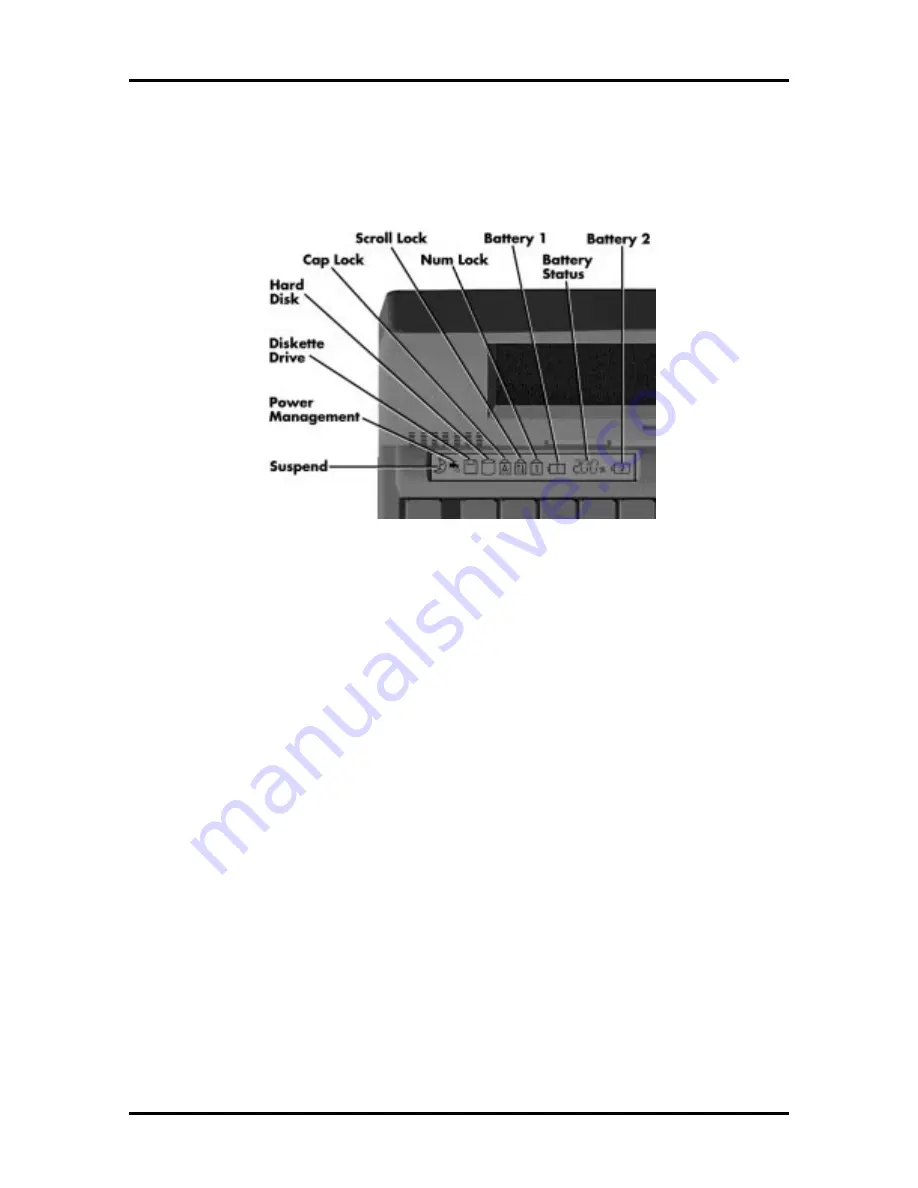
The NEC Versa 6000 status bar is located in the upper left corner of the keyboard panel.
Figure 2-12 shows the status bar.


Figure 2-12   Status Bar Location

Status Icons

The NEC Versa 6000 uses eight icons to let the user determine system status, as follows.

■  

Suspend — appears when the system is in Suspend mode.

■  

Power Management — shows current power management mode.

■  

Diskette Drive — appears when the NEC Versa writes data to, or retrieves data
from a diskette.

■  

Hard Disk — shows when the NEC Versa writes data to, or retrieves data from
the system’s hard disk.

■  

Caps Lock  — appears when caps lock is used.

■  

Scroll Lock — indicates that scroll lock is used.

■  

Num Lock — indicates that Num lock is used.

■  

Battery Status — displays the percentage of battery power available.

 

Battery 1 appears when you have one or more batteries installed.

 

Battery 2 appears when you have an optional battery installed in the VersaBay
II.


Summary of Contents for VERSA 6000 Series

Page 1: ...ct s discussed in this document are warranted in accordance with the terms of the Warranty Statement accompanying each product However actual performance of each such product is dependent upon factors such as system configuration customer data and operator control Since implementation by customers of each product may vary the suitability of specific product configurations and applications must be ...

Page 2: ...pliance power consumption and system memory specifications Section 2 Setup and Operation takes the authorized service technician or dealer from unpacking to setup and operation The section includes a description of operating controls setting parameters and accessing the NEC bulletin board system BBS Section 3 Troubleshooting and Repair includes troubleshooting procedures Section 4 Field Service Gu...

Page 3: ... Hardware Overview Right Side 1 9 Hardware Overview Left Side 1 10 PC Card Slots 1 10 Battery Compartment 1 11 Hardware Overview Rear Side 1 11 Keyboard Mouse Port 1 11 Parallel Port LPT1 1 11 Rear Infrared Port 1 12 Expansion Port 1 12 Monitor Video Port 1 12 Serial Port COM 1 1 12 Hardware Overview Internal Components 1 12 Battery Pack 1 12 Hard Disk Drive 1 12 Diskette Drive 1 13 6x CD ROM Read...

Page 4: ...1 Interrupt Controllers 1 21 Power Management Overview 1 22 System Power Management 1 23 Local Power Management 1 23 Plug and Play 1 24 Specifications 1 25 Section 2 Setup and Operation Unpacking the System 2 1 Hardware Setup 2 1 Cable Connections 2 2 Power Sources 2 3 Using the AC Adapter 2 4 Using the Main Battery Pack 2 4 Determining Battery Status 2 5 When to Change the Battery 2 6 Battery Han...

Page 5: ...p Screen 2 20 Setup Keys 2 21 Changing Setting Parameter Settings 2 21 Parameter Options 2 22 Parameter Descriptions 2 24 Time Date 2 24 Drives 2 24 Peripherals 2 25 Power Savings 2 25 Security 2 26 Security Options 2 26 Setting an Initial Password 2 26 Using the System Password 2 27 Keyboard Lock 2 27 PowerPanel Overview 2 27 Automatic Power Saving Features 2 28 Section 3 Troubleshooting and Repa...

Page 6: ... Type 4 8 LCD and Top Cover 4 10 Power Button IR Board Keyboard 4 12 LCD Status Bar VersaGlide Assembly Metal Keyboard Support 4 14 Bridge Battery CMOS Battery Buzzer 4 15 CPU Board Modem Board 4 16 Heat Shield Sound Board Microphone Assembly 4 17 I O Board 4 18 Illustrated Parts Breakdown 4 19 Service Information 4 23 Technical Support 4 23 Product Information 4 24 Ordering Information from FastF...

Page 7: ...2 7 2 7 Inserting the Battery Pack 2 8 2 8 Replacing the Cover 2 8 2 9 Connecting the Car DC Adapter 2 10 2 10 Keyboard Panel LEDs and Controls 2 11 2 11 Right Side Panel Controls Ports 2 11 2 12 Status Bar Location 2 13 2 13 Locating the Switch Settings 2 16 4 1 Removing the Drive Bay Cover 4 5 4 2 Removing the Hard Disk Drive 4 6 4 3 VersaBay II Release Latches 4 7 4 4 Removing the Standard Disk...

Page 8: ...Performance Default Settings 1 24 1 7 Specifications 1 25 2 1 I O Connector Descriptions 2 3 2 2 Control and Switch Functions 2 12 2 3 FnKey Operations 2 14 2 4 POST Error Messages 2 18 2 5 Setup Key Functions 2 21 2 6 Setup Parameters 2 22 2 7 Automatic Power Saving Features 2 28 3 1 Quick Troubleshooting 3 1 3 2 BIOS Informational Messages 3 4 3 3 BIOS Beep Codes 3 6 4 1 NEC Versa 6000 Series Di...

Page 9: ... 4 A 6 Power Connector A 4 A 7 Hard Disk Drive Connector A 5 B 1 LCD Display Mode Setting 800x600 TFT Color LCD Simultaneous CRT Display B 1 B 2 CRT Display Mode CRT Only B 3 B 3 Panning Video Mode 800x600 TFT Color LCD and Simultaneous CRT Display B 4 ...

Page 10: ...nowledge DC direct current DIP dual in line package DLAB Divisor Latch Address bit DMA direct memory access DMAC DMA controller DOS disk operating system DRAM dynamic RAM DTE data terminal equipment ECC error checking and correction EDS error detecting system EGA Enhanced Graphics Adapter EMS Expanded Memory Specification EPP enhanced parallel port EPROM erasable and programmable ROM EVGA Enhanced...

Page 11: ... Center PAL programmable array logic PC personal computer PCB printed circuit board PFP plastic flat package PIO parallel input output pixel picture element PJQFP plastic J lead quad flat pack PLCC plastic lead chip carrier PLL phase lock loop p p peak to peak PPI programmable peripheral interface PROM programmable ROM QFP quad flat pack RAM random access memory RAMDAC RAM digital to analog RAS ro...

Page 12: ...eceiver transmitter V volt Vdc volts direct current VESA video electronics standards association VFO variable frequency oscillator VGA Video Graphics Array VLSI very large scale integration VRAM virtual RAM W watt µf microfarad µPD microprocessor µs microsecond Ω ohm ...

Page 13: ... Series notebook computers are available in the following models Table 1 1 Model Configurations Configuration NEC Versa 6000H NEC Versa 6030H NEC Versa 6030X CPU Pentium P54LM 100 MHz Pentium P54CSLM 133 MHz Pentium P54CSLM 133 MHz On Board DRAM 16 MB 16 MB 16 MB Video Memory 2 MB 2 MB 2 MB Hard Disk Drive 1 08 GB 1 35 GB 1 44 GB Color LCD 11 3 SVGA TFT Color Display 12 1 SVGA TFT Color Display 12...

Page 14: ...t ad justs screen brightness Figure 1 2 LCD Panel The NEC Versa 6000 series computer features the following LCD types 11 3 inch SVGA TFT active matrix Thin Film Transistor TFT Cold Cathode Flourescent Tube CCFT Super VGA SVGA backlit color LCD 0 29 mm dot pitch 18 bit digital interface 800 x 600 resolution and 256 000 colors 12 1 inch SVGA TFT high resolution active matrix TFT CCFT SVGA backlit co...

Page 15: ...ent settings See Section 2 Setup and Opera tion for information on using these settings In addition the automatic LCD status sense feature conserves the backlight When the LCD is closed the backlight shuts off saving battery power Power Button Slide the power button to the right to power on and power off the computer The power button is a smart switch meaning that it recognizes when the system is ...

Page 16: ...en color whenever the computer s power is on Figure 1 4 LCD Status Bar Status Icons The following list defines the status icons displayed in the system status bar Suspend appears when the system is in Suspend mode Suspend mode con serves system power by shutting down devices in the system while retaining data and system status Power Management shows the current power management mode in use in clud...

Page 17: ...ears when you have an optional battery installed in the VersaBay II Keyboard The built in 83 key keyboard U S or 79 key keyboard UK and Germany uses the stan dard QWERTY format The keyboard provides 12 function keys and 8 cursor control keys with an Fn key for ROM based key functions The numeric keypad is embedded in the stan dard key layout Figure 1 5 Keyboard Layout ...

Page 18: ...VersaGlide pad and the cursor follows The buttons on either side of the NEC Ver saGlide allow the user to select or deselect menu items Tap and double tap are supported on the VersaGlide pad The NEC VersaGlide is the system s default pointing device unless a PS 2 mouse is in stalled If an external mouse is installed then the NEC VersaGlide is deactivated A serial mouse is not supported Figure 1 6 ...

Page 19: ...ng the release latches on the bottom of the unit Figure 1 7 NEC VersaBay II Location Infrared IR Front Assembly The front IR assembly is connected to the I O board via connectors P7 The rear IR assem bly is discussed later in this section The front IR assembly consists of a small board with infrared LEDs The board allows the NEC Versa 6000 series computer to communicate with other infrared ready c...

Page 20: ... front IR assembly go into Setup to change the default setting to the front IR assembly When the NEC Versa 6000 is docked to the optional NEC Versa Docking Station 6000 the rear IR assembly is automatically disabled and the front enabled Figure 1 8 Front IR Assembly Location Figure 1 9 Rear IR Assembly Location ...

Page 21: ...contains a 1 gigabyte GB 1 3 GB or 1 44 GB hard disk drive To access the hard disk drive simply turn the system over and lift up the hard disk drive bay cover release latch while pushing the cover away from the system Kensington Lock Gives the user the option to add an optional Kensington Lock Volume Control Controls speaker volume Headphones Connects external headphones or speakers to the NEC Ver...

Page 22: ...cription of the hardware on the left side of the NEC Versa 6000 Figure 1 11 Left Side Features PC Card Slots The PCMCIA slot compartment houses two card slots that support two PCMCIA Type II devices or one Type III device For Type III cards insert into the upper slot Insert the card with the pin sockets facing towards the drive and the label facing up To remove the PCMCIA card push on the eject bu...

Page 23: ...description of the hardware on the rear of the NEC Versa 6000 Figure 1 12 Rear Features Keyboard Mouse Port Use the standard PS 2 port to connect an external PS 2 style mouse or a PS 2 style key board to the system With an optional Y cable adapter you can connect both a mouse and a keyboard at the same time Parallel Port LPT1 The 25 pin printer port provides a parallel interface to which you can c...

Page 24: ... serial port provides a serial interface to which you can connect an RS 232C de vice such as external serial pointing device or modem HARDWARE OVERVIEW INTERNAL COMPONENTS Review the following sections for a description of the system s internal hardware Battery Pack The system uses a rechargeable lithium ion Li Ion battery as its transient power source The battery pack installs in the compartment ...

Page 25: ...e VersaBay II slot The CD ROM reader is assigned to the next available drive letter The CD ROM reader operates at different speeds depend ing on whether the CD in use contains data or music This improves video and sound qual ity CPU Board The 100 MHz or 133 MHz CPU board G8UUR G8UURB is an L shaped board situ ated next to the audio ports In addition to the CPU this board houses the front and rear ...

Page 26: ...und Board The sound board G8UUT provides the NEC Versa 6000 series system with its audio ca pabilities via line in line out jacks and headphone microphone jacks It is situated on top of the I O board Figure 1 14 Sound Board Layout ...

Page 27: ...al modem transmits data at a rate of 28 000 bits per second integrating built in error control The modem provides one standard phone connector and one cellular phone connector for transforming the notebook into a speakerphone NEC provides two analog phone cables one is a spare for convenience The built in modem is also cellular capable To use the computer s cellular phone connec tor the user needs...

Page 28: ...s connected to the CPU board via connector P15 The AC adapter maintains voltage in the bridge battery when the system is powered on or off The bridge battery provides 6 Volts 60 mAH System Memory The system board provides 16 MB of standard random access memory RAM Optional memory boards with a value of 8 16 32 or 64MB can be added to increase system memory up to a maximum of 80 MB 70 ns Fast Page ...

Page 29: ...0E7FFFh 32 KB Upper Memory Block option cards or UMB 000E8000h 000EFFFFh 32 KB Upper Memory Block UMB only 000F0000h 000FFFFFh 64 KB System BIOS ROM 00100000h 02FFFFFFh 47 MB Extended Memory SYSTEM VIDEO The system s LCD operates using the Chips and Technologies 65550 VGA Controller Video signals travel from the controller through the system s 15 pin D SUB connector us ing 5 volts System video int...

Page 30: ...or an external modem The serial port address is 3F8h and the interrupt level is IRQ04 NEC VERSA 6000 SERIES CHIP SET Refer to Table 1 3 for a quick summary of the chip types used in the system See the Ab breviations section at the beginning of this manual for a translation of chip technologies Table 1 3 NEC Versa 6000 Series Chip Types and Technologies Chip Manufacturer Description Technology Inte...

Page 31: ...in plastic lead chip carrier PLCC The chip allows easy updates to the system s BIOS if needed More specifically the ROM is flashed electroni cally installing the latest BIOS revisions to the system It is possible to reprogram the BIOS up to 100 000 times See Section 2 Setup and Operation for BIOS update procedures The N28F020 provides the system upgrade capability as well as the following 256 KB m...

Page 32: ...he controller changes 8 bit parallel data into serial data and writes the data to the diskette Conversely the serial data is transmitted from the diskette into parallel data where it remains until the read operation takes place Additional PC87338VLJ chip operations include ISA compatibility low power CMOS with enhanced power down mode Keyboard Controller The keyboard controller M38813E4HP supports...

Page 33: ...tick quad timer Interrupt Controllers Using interrupts it is possible to change the system s code sequence To change the se quence reassign the interrupt levels Fifteen interrupts can be used with a cascade connec tion of 8259INTC x 2 Interrupt level assignments 0 through 15 are listed in Table 1 4 in order of decreasing pri ority Table 1 4 Interrupt Controllers Controller Master Slave Priority Na...

Page 34: ...features to function automatically or activate them manually with the keyboard or a button It is wise to keep Power Management features enabled even when using AC power The system arrives set up with many power saving features already enabled See the follow ing table Table 1 5 Automatic Power Saving Features Device Default Timeout Comment LCD backlight 2 minutes Backlight turns off after there is ...

Page 35: ... RAM System RAM is put into a slow refresh state The system resumes Active mode when you press the Suspend button the system detects a modem ring or the system is set to resume at a certain time of day The system will not resume Active mode if a PCMCIA modem detects a ring Sus pend mode lets you save power without first saving the working data Press the Suspend button to enter Suspend mode when yo...

Page 36: ...LCD and Hard Disk Drive Table 1 6 shows NEC Versa 6000 series Maximum Performance default power man agement timers Table 1 6 Maximum Performance Default Settings Power Management Mode Automatic Suspend Hard Disk Timer LCD Panel Timer Longest Battery Life 10 minutes 30 seconds 2 minutes Highest Performance 30 minutes 10 minutes 10 minutes Custom 10 minutes 30 seconds 2 minutes PLUG AND PLAY The NEC...

Page 37: ...nctions Device Slots Two PCMCIA slots that support up to two optional cards oriented one on top of the other One 3 1 2 inch x 0 75 inch high slot side access for standard hard disk drive One 3 1 2 inch x 0 75 inch high slot front access for standard 1 44 diskette drive One memory slot for optional memory card located on bottom of system in the hard disk drive bay Power 100 to 240 Vac at 50 or 60 H...

Page 38: ... Support Serial 1 port 9 pin D sub Infrared 2 ports 1 on front of system 1 on back IrDA 1 compatible VGA 1 port 15 pin high density D sub External Keyboard External Mouse 1 port PS 2 6 pin MiniDin exclusionary use or both supported with optional Y adapter Expansion 1 port for optional NEC Docking Station 6000 optional PortBar 6000 Modem 2 pin tip ring connector 9 pin cellular phone connector Mono ...

Page 39: ...sa 6030X 12 1 inch high resolution active matrix Extended Graphics Array XGA color display 1024 x 768 pixels 0 24 mm dot pitch 256 000 18 bits colors Internal Device Support Diskette Drive 3 1 2 inch 1 44 MB thin height Hard Disk Drives IDE interface built in 2 1 2 inch x 1 inch high thin height System ships with the 1 GB 1 35 GB or 1 44 GB hard disk drive 6x CD ROM Reader User removable six speed...

Page 40: ...eling Software CompuServe America Online free trial access VideoSaver MPEG Presentation Software SystemSoft PCMCIA Drivers with CardWizard Recommended Environment Operation Temperature 41 to 104 F 5 to 35 C Relative Humidity 20 to 80 No condensation Storage Temperature 4 to 104 F 20 to 40 C Relative Humidity 20 to 80 No condensation Administrative Compliance U S FCC UL Canada CSA DOC Germany VDE T...

Page 41: ...k the system The carton contents include the system AC adapter AC power cord battery soft ware diskettes and user documentation HARDWARE SETUP When connecting power and signal cables do the following 1 The power switch turns the system on or off Slide the switch right to turn it on slide the switch again to turn it off 2 Connect the AC adapter cable to the power port on right side of your NEC Vers...

Page 42: ...e right to power on the computer Figure 2 2 Powering on the System NOTE If operating the system on DC power verify that the system has a charged battery pack installed Cable Connections Figure 2 3 shows the external connectors for the system Where appropriate secure cables by tightening the cable holding screws Table 2 1 describes the I O connectors on the rear of the system For pin assignments se...

Page 43: ... or print to an IR equipped printer without using cables Expansion Connector Provides a 75 pin connector to attach the optional NEC Docking Station 6000 Monitor Port Connects to a 15 pin external CRT Serial Port Connects to an RS 232C device POWER SOURCES The NEC Versa 6000 can be powered using three different sources as follows the AC adapter connected to an electrical wall outlet using AC power ...

Page 44: ... a rechargeable Lithium Ion Li Ion battery pack Battery power for lasts for approximately two to four hours with power management features en abled The battery pack is easy to install and remove The NEC Versa 6000 system integrates two tools to help the user keep track of the main or an optional battery s power level These include the percentage LEDs described earlier and the battery gauge in Powe...

Page 45: ...n the battery bay Read the precautions printed on the battery and in the online Basics Determining Battery Status You can determine battery status via the battery icon in the status bar discussed earlier If you have one battery pack installed one battery icon appears If you have two battery icons two battery packs appear A blinking battery icon indicates that the battery is charging A fast blinkin...

Page 46: ...ormance and shorten battery life Clean the battery terminals with a dry cloth when they get dirty Keep the battery out of the reach of children Replacing the Battery Pack Replace the battery pack installed in your NEC Versa system as follows NOTE Use Li Ion batteries in the NEC Versa computer for which they are designed Also in stalling another manufacturer s battery or using a combination of very...

Page 47: ...ing the Cover 4 Place a finger in the notch on the battery and lift the battery out of the system WARNING Always lift the battery out of the system by the notch Failure to do so can damage the battery terminals Figure 2 6 Removing the Battery ...

Page 48: ...ry Lower the notched end of the battery into the battery compartment Figure 2 7 Inserting the Battery Pack 6 Replace the battery bay cover as follows Align the tabs on the bay cover with the grooves on the system chassis Lower the cover onto the bay and slide it into place Figure 2 8 Replacing the Cover ...

Page 49: ... away from water Keep metal objects away from battery terminals Metal objects in contact with the terminals can cause a short circuit and damage If the battery leaks If the battery leaks onto skin or clothing wash the area immediately with clean water Battery fluid can cause a skin rash and damage fabric If battery fluid gets into eyes DO NOT rub rinse with clear water immediately and consult a do...

Page 50: ...to be aware of the simple things you can do to extend the life of the system s main battery One way is to keep the LCD backlight setting to Standard instead of Full You can toggle between these two settings by pressing the function keys Fn F5 Or slide the backlight control to a dimmer level Using the DC Car Adapter Another way to power the NEC Versa 6000 is via car battery power using the optional...

Page 51: ...section describes system controls the LEDs and function keys Refer to Figure 2 10 and Figure 2 11 to locate system controls and switches Table 2 2 de scribes the controls Figure 2 10 Keyboard Panel LEDs and Controls Figure 2 11 Right Side Panel Controls Ports ...

Page 52: ...se Latch Lift latch to remove the hard disk drive installed in the system Kensington Lock Enables the user to add an optional Kensington Lock to prevent unauthorized use of the computer Volume Control Controls the speaker volume Headphones Connects external headphones or speakers to the NEC Versa 6000 Plugging in headphones disables the built in system speakers Line Out Connect this port to a Line...

Page 53: ...ows current power management mode Diskette Drive appears when the NEC Versa writes data to or retrieves data from a diskette Hard Disk shows when the NEC Versa writes data to or retrieves data from the system s hard disk Caps Lock appears when caps lock is used Scroll Lock indicates that scroll lock is used Num Lock indicates that Num lock is used Battery Status displays the percentage of battery ...

Page 54: ... Lock On Off Smart Power Switch Provides an automatic feature that prevents you from accidentally powering off the NEC Versa 6000 and losing your data while your system is in Suspend mode The smart power switch senses that the system is in Suspend mode and prevents you from directly powering off the system when you press the power switch To power off the system from Suspend mode 1 Press the Suspen...

Page 55: ...eserved for factory use Switch 4 Reserved for factory use Updating the System BIOS Use the following steps to update the NEC Versa 6000 system BIOS with the BIOS Update diskette BUD Specifically the BIOS is the code transmitted onto your system s micro processor or central processing unit CPU NOTE You only need to update the BIOS if NEC makes significant improvements or fixes to the current system...

Page 56: ...nable BIOS reprogramming 5 Replace the hard disk drive and the compartment cover Now you are ready to begin the actual update procedure using the following steps 6 Make sure that power is off and not docked Insert the BIOS Update diskette into diskette drive A 7 Power on the computer with the diskette in drive A The computer boots and automatically loads the utility A message similar to the follow...

Page 57: ...SELF TEST POST Each time the system is powered on the system checks the working status of components through an automatic power on self test POST The test checks the system configuration for any discrepancies One beep means that POST is successful If any problems in data transfer or hardware exist an error message appears If the message is an Invalid Configuration message press F2 to enter the Set...

Page 58: ...e hard disk Or insert a bootable disk in drive A and press F2 Non system disk or disk error replace and press any key when ready Remove the diskette from drive A and press any key to start the system from the hard disk No boot device available press F2 to run Setup Press F2 start Auto Setup and change the hard disk type to the correct setting Exit and save Auto Setup Invalid configuration informat...

Page 59: ...It also provides the following functions sets date and time signals any hardware discrepancies during POST via error messages verifies that any optional memory that you installed was installed correctly integrates security features Setup also includes security features that protect your system from unauthorized use Accessing Setup To access Setup press F2 at the power on prompt With an Error at PO...

Page 60: ...the IDE adapter Item Specific Help Item Specific Help 09 24 07 07 07 1996 1 44 MB 3 1 2 Not Installed Enabled Disable No F1 Help ESC Exit Select Item Select Menu Change Values Enter Select _ F9 Defaults for Page F10 Previous Values Sub Menu Menu Bar The top line of the screen Each of the five selections displays its own screen Parameters The left part of the screen This area lists parameters and t...

Page 61: ...hange parameter settings NOTE Selecting incorrect values may cause a system boot failure Load Setup default values to recover 1 Select a parameter menu from the menu bar by moving the cursor to the word that represents the screen you want to display For example to select Peripherals press the arrow key until the word Peripher als is highlighted A screen appears with the current setting for each pe...

Page 62: ...talled 1 2MB 5 25 Not Installed 1 44MB 3 5 1 2MB 5 25 Internal Hard Drives Master Enable Auto Disable BIOS Defined None CD User Slave None BIOS Defined Auto CD User Docking Station Hard Drives Docking Station Master Docking Station Slave Boot Docking Station IDE System Memory Extended Memory Disable None None No 640K 15360KB Enable BIOS Defined Auto CD User BIOS Defined Auto CD User Yes 19456KB w ...

Page 63: ... Disabled is selected Sound Power is Off Sound IRQ Low 8 bit DMA High 16 bit DMA Docking Station MPU 401 Docking Station Joy Stick 5 1 5 Reconfigurable Disabled when mobile Enabled Disabled when mobile 7 10 3 7 Disabled I O address 300 I O address 330 Disabled Security User Password Set Password Password on boot Password on resume Disabled Press Enter Disabled Disabled Enabled Enabled Enabled Powe...

Page 64: ... as Windows for Workgroups or DOS Doing so disables the device Can be in the docking station or VersaBay II Parameter Descriptions Read the following for an understanding of each parameter s function Time Date Use this option to set the time and date The settings remain in memory even after you turn off system power To set the time enter the current hour minute and second in hh mm ss 24 hour forma...

Page 65: ...ption the system uses the power management mode on or off you set using the Power Management option Power Savings A Highest Performance setting provides the greatest sys tem performance Longest Battery Life provides maximum power saving and Off disables all power management timers You can also customize the system s power management by selecting Custom Settings and entering values for system timeo...

Page 66: ...ssword must be entered before entering Auto Setup This feature allows only authorized access to system parameters Use the following procedures to set an initial password 1 Select the Security option in Setup 2 Select Set Password by pressing Enter 3 At the prompt enter a password up to seven characters long Another window appears with a prompt to reenter your password for verification Write your p...

Page 67: ...the lock can be enabled or disabled To lock the keyboard press Ctrl Alt Back Space To unlock the keyboard enter the password If the password is removed this option is no longer available POWERPANEL OVERVIEW The NEC Versa 6000 system gives the user a tool that simplifies changing the system con figuration settings discussed previously in this section including power management PowerPanel appears in...

Page 68: ...can toggle be tween Highest Performance Longest Battery Life Custom Values and Off You can mod ify the custom level for your specific working environment using Custom Values Default values change depending on the type of power management you use Table 2 7 Automatic Power Saving Features Device Default timeout Description LCD backlight 2 min When no keyboard or NEC VersaGlide input occurs for the s...

Page 69: ...lso that the AC adapter is plugged into a properly grounded AC power outlet If using the battery as main power source check if the battery pack is of the right type charged and is inserted correctly Check the powerboard of the system Is it inserted into the main board connector properly Otherwise replace the powerboard Data on the LCD is unreadable Adjust the brightness controls on the right side ...

Page 70: ...g malfunctions Check the connections of all internal devices Replace main board Diskette drive does not work Check if floppy drive cable is connected properly Check diskette type if correct and not faulty Replace diskette drive Replace main board Hard disk drive malfunction Check if hard disk drive is set properly on CMOS SETUP Check drive cables and connections Check if disk drive is good Replace...

Page 71: ...rted properly Remove VersaGlide and clean it t Check the keyboard controller chip for any cold or loosed soldering Replace the main board Serial device does not work If using serial mouse check if VersaGlide is disabled under CMOS Setup Check if mouse driver is installed properly Check if serial device is connected properly Replace serial device Check the I O controller chip on the main board for ...

Page 72: ... press the power switch to power on the system INFORMATIONAL MESSAGES This section lists the messages that provide information to the user but require no action Table 3 2 BIOS Informational Messages Message Meaning nnnK System Memory The amount of system memory that tested successfully nnnK Cache SRAM Cache SRAM Memory nnnK Extended The amount of extended memory that tested successfully Memory tes...

Page 73: ...ritten the test is considered a failure 2 Rolling ones test Several patterns are constructed These patterns represent a one rolling through the given location For example to roll a one through three bits the following patterns would be constructed 001 010 011 100 101 110 and 111 The patterns are written to the location and then read back one by one If the value read does not match the value writte...

Page 74: ...er 0 are read and accumulated by ORing them into the values read so far It is expected that during the time period all bits are set 1 3 1 08h RAM refresh verification test in progress or failure Over a period of time the refresh bit bit 4 in port 60h is read and tested The refresh bit should toggle from 0 to 1 then 1 to 0 within the time period Failure will result in system halt none 09h First 64K...

Page 75: ...is tested with a rolling ones test and a pattern test If any of the rolling ones tests fail then the BIOS reports the specific bit that failed To determine the bit number from the diagnostic code subtract 10h For example if 12h is displayed at the diagnostic port bit 2 failed Failure results in a system halt 3 3 1 20h Slave DMA register test in progress or failure Pattern test of channels 1 throug...

Page 76: ... 3 2 4 27h Keyboard controller test in progress or failure The self test command AAh is issued to the 8042 keyboard controller and the results are monitored Failure results in a system halt None 28h CMOS RAM power failure and checksum calculation test in progress The power fail bit in CMOS RAM is tested and the lower CMOS RAM area is being checksummed A failure does not result in system halt None ...

Page 77: ... 32h Color monitor 40 column operable No specific test is performed just indicates that the BIOS believes a color monitor is installed and is operating The mode has been set to 40 column as selected by the user in CMOS RAM none 33h Color monitor 80 column operable No specific test is performed just indicates that the BIOS believes a color monitor is installed and is operating The mode has been set...

Page 78: ...y above the first 64K is tested with a rolling ones test and a pattern test All success and failure messages are displayed on the screen and POST will continue 4 3 2 3Ah Programmable interval timer channel 2 test in progress or failure Over a period of time the current count values in timer 2 are read and accumulated by ORing them into the values read so far It is expected that during the time per...

Page 79: ... Beep Code Diagnostic Code Description Test Performed 4 4 3 3Eh Math coprocessor test in progress or failure An integer load and store is performed with the math coprocessor If the values do not match an error message will be displayed and POST will continue ...

Page 80: ...nt inside the system unit and LCD even after the system is turned off Cleaning the Notebook s Exterior Use the steps below to clean the outer surface of the system 1 Power off the system and remove the primary battery pack Unplug all cables connected to the system 2 Wipe the outside of the system unit keyboard and display with a soft clean cloth Remove stains with a mild liquid detergent like a co...

Page 81: ... Periodically use a head cleaning diskette in the floppy diskette drive to prolong the life of the drive and to help maintain data integrity Here are some maintenance procedures to use when servicing a hard disk Always back up the data files from the hard disk Run a virus detecting program for possible virus infested area on the hard disk Use SCANDISK to correct any errors found in the directory a...

Page 82: ... the battery leads or connect the battery with reversed polarity Never attempt to charge the battery packs in any way other than as described in this manual and the User s Guide Always charge the battery packs as soon as possible after a low battery indication Maintaining the LCD Quality When it comes to screen problems heat plays a big part After a good working session the typical routine is to s...

Page 83: ...ee Page 1 Hard Disk Drive 4 5 2 Diskette Drive installed in VersaBay II 4 7 3 Main Battery Pack Li ION type 4 8 4 LCD and Top Cover 4 10 5 Power Button IR Board Keyboard 4 12 6 LCD Status Bar VersaGlide Assembly Metal Keyboard Support 4 14 7 Bridge Battery CMOS Battery Buzzer 4 15 8 CPU Board Modem Board 4 16 9 Heat Shield Sound Board Microphone Assembly 4 17 10 I O Board 4 18 When disassembling t...

Page 84: ...sed in the VersaBay II Check the top of the hard drive for a blue dot If the drive case has the blue dot on it you can use the drive in either the drive bay or the VersaBay II 1 Check that the NEC Versa power is off 2 Turn the NEC Versa 6000 upside down with the front of the unit facing you 3 Remove the drive cover as follows Locate the drive cover release latch Push the drive cover release latch ...

Page 85: ...sest to the connector While maintaining pressure slide the drive towards the front of the system CAUTION Do not lift the drive out of the sys tem before releasing it from the system connec tor Doing so can damage the connectors Once the drive is disconnected lift the drive up and out of the system Figure 4 2 Removing the Hard Disk Drive ...

Page 86: ...t facing you 3 Locate the VersaBay II release latches on the bottom of the unit Figure 4 3 VersaBay II Release Latches 4 Slide the front latch towards the hard disk drive side of the system and hold it 5 Push the middle latch towards you until the diskette drive pops part way out of the unit 6 Continue to hold the latch near the front of the system to the left and pull the diskette drive the rest ...

Page 87: ...ry Pack Li Ion Type Remove the main battery pack as follows NOTE Use Li Ion batteries in the NEC Versa computer for which they are designed Also in stalling another manufacturer s battery or using a combination of very old and new batteries can deteriorate battery and equipment performance 1 Save your files exit Windows and press the Suspend button or turn off system power 2 Close the LCD and turn...

Page 88: ...away from the system Figure 4 5 Removing the Battery Compartment Cover 4 Place a finger in the notch on the battery and lift the battery out of the system NOTE Always lift the battery out of the system by the notch Failure to do so can damage the battery terminals Figure 4 6 Removing the Battery ...

Page 89: ...rn the computer over with the VersaBay II slot facing towards you Locate the 10 screws that secure the bottom base unit cover In all there are 2 long type screws 2 medium type screws and 6 short type screws Figure 4 7 Removing the Bottom Base Screws Remove the ten screws Using a flat head screwdriver carefully detach the bottom base unit cover from the top cover ...

Page 90: ...he two LCD cables from connectors P16 and CN3 on the main board Figure 4 8 Disconnecting the LCD Connectors 4 Lift the top cover and LCD up and off of the base unit assembly NOTE Remove the top cover carefully so that you don t damage the plastic ...

Page 91: ...in place primarily by the computer s top cover Once the top cover is removed just lift the power button out of its retaining inserts 3 Remove the IR board as follows Remove the screws securing it in place Locate the IR board cable that attaches to connector P7 on the CPU board Use a flat head screwdriver to push open the connector tabs Lift up the IR board Figure 4 9 Removing the Power Button IR B...

Page 92: ... keyboard as follows Locate the two ribbon cables that attach to the CPU board via connectors P3 and P4 Figure 4 10 Disconnecting Keyboard Cables Use a flat head screwdriver to push open the connector tabs Lift the keyboard out of the base unit ...

Page 93: ...le that attaches to the CPU board via connector P5 Use the tip of a screwdriver and carefully open the connector tabs Lift up the LCD status bar 3 Remove the VersaGlide assembly as follows Locate the cable on the VersaGlide assembly Disconnect the cable from connector P6 on the CPU board Lift the VersaGlide out of the base unit 4 After removing the LCD status bar and VersaGlide lift the metal keyb...

Page 94: ...d LCD status bar VersaGlide metal keyboard support 2 To remove the bridge battery disconnect the cable from connector P15 on the I O board and remove the bridge battery 3 Remove the CMOS battery as follows Locate the cable on the CMOS battery Disconnect the cable from connector P14 on the I O board and lift the CMOS battery out of the base unit Figure 4 12 Removing Bridge Battery CMOS Battery and ...

Page 95: ...oard as follows 1 Remove the following as previously described LCD top cover keyboard LCD status bar VersaGlide metal keyboard support 2 Disconnect the bridge battery CMOS battery and buzzer from the I O board 3 Remove the two screws that secure the CPU board to the base unit 4 Gently lift the CPU board out of connectors P2 and P7 on the I O board Figure 4 13 Removing the CPU Board ...

Page 96: ...ips or circuitry on the board 6 Lift the modem board out of connectors P1 and P2 Heat Shield Sound Board Microphone Assembly Remove the heat shield sound board and or the microphone assembly as follows 1 Remove the following as previously described LCD top cover keyboard LCD status bar VersaGlide metal keyboard support bridge battery CMOS battery buzzer speaker and CPU board ...

Page 97: ...the I O board 4 To remove the microphone assembly locate the cable attached to the assembly 5 Disconnect the cable from CN4 on the I O board and lift the microphone assembly out of the base unit Figure 4 14 Heat Shield Sound Board Microphone Assembly I O Board Remove the I O board as follows 1 Remove the following as previously described LCD top cover keyboard LCD status bar VersaGlide metal keybo...

Page 98: ... ILLUSTRATED PARTS BREAKDOWN The next section contains the NEC part numbers and illustrated parts breakdown IPB fig ure for the NEC Versa Series 6000 Figure 4 16 shows the system exploded view diagram or IPB Table 4 2 lists field replaceable parts and corresponding part numbers Review the entire exploded diagram to see how each part is connected or assembled Try to sub divide the entire diagram pa...

Page 99: ...4 20 Field Service Guidelines Figure 4 16 NEC Versa 6000 Ilustrated Parts Breakdown ...

Page 100: ...250 001A 12 Rear IR Board Assembly G8UUV 808 875213 001A 13 VersaGlide Assembly 808 874649 002A 14 VersaGlide Cable 808 742261 001A 15 LCD Status Bar 158 057234 000 16 Logo NEC 136 600325 A 17 Intel Inside Sticker 158 030621 001 18 Logo P55 100 MHz SVGA 11 3 Logo P55 100 MHz SVGA 12 1 Logo P55 100 MHz XVGA 12 1 158 030781 006 158 030781 007 158 030781 008 19 LCD Top Cover Assembly SVGA 11 3 LCD To...

Page 101: ... 5 inch 1 44 MB Diskette Drive 134 507049 0010 30 Main Battery Li Ion 804 021248 001A 31 Bottom Base Assembly Plastic 136 238585 001A 32 6x CD ROM Reader 136 269134 001A 33 Shipping Carton 158 041004 000 34 Left Packaging Foam Cushion 158 041007 000 35 Right Packaging Foam Cushion 158 041007 001 36 NEC Versa 6000 Series User s Guide 819 200069 000 Rev 00 37 NEC Versa 6000 Series Service and Refere...

Page 102: ...ts or technical support Service Contracts TAC Technical Assistance Center technical support for NASC and NEC sales representatives only TSC Technical Support Center technical support for everyone else FastFactsTM automated service that sends the latest information about NEC products to the fax machine 24 hours a day In the U S call 1 800 366 0476 Outside U S 1 708 860 9550 Ext 2621 Canadian Inquir...

Page 103: ...tor Products Catalog 2 CD ROM Hardware and Software Printers and Disk Drive Products Catalog 3 Laptop Desktop and Server Computer Products Catalog 9 Price and Configuration Index ORDERING INFORMATION FROM FASTFACTS Order information from FastFacts as follows 1 Check that the fax machine is on 2 Locate the document part number 3 Using a touch tone telephone call 1 800 366 0476 U S and Canada only F...

Page 104: ...sted will be sent automatically to your fax machine If Fast Facts attempts to send the second order before the first order is completed the order could be canceled After three tries FastFacts assumes that the line is busy and will not process the order ...

Page 105: ...endix A Connector Locations and Pin Assignments Figure A 1 and Table A 1 show CPU board connectors The remaining tables provide pin assignments for additional system connectors Figure A 1 CPU Board Layout ...

Page 106: ...scription P3 and P4 Keyboard Connectors P5 LCD Status Bar P6 VersaGlide Assembly Connector P7 Rear Infrared Assembly Connector P11 and P12 Front Infrared and LED Assembly Table A 2 Keyboard Mouse Connectors Pin Signal 1 KeyboardData 2 MouseData 3 Ground 4 5V 5 Keyboard Clock 6 Mouse Clock ...

Page 107: ... Transmit Data 4 Data Terminal Ready 5 Ground 6 Data Set Ready 7 Request to Send 8 Clear to Send 9 Ring Indicator Table A 4 CRT Connector Pin Assignments Pin Signal 1 Red 2 Green 3 Blue 4 OPT1 5 Ground 6 Ground 7 Ground 8 Ground 9 5V PnP VESA Vcc 10 Ground 11 OPT2 12 PnP VESA Data 13 Horizontal Sync 14 Vertical Sync 15 PnP VESA Clock ...

Page 108: ...Signal 1 Strobe 2 Data Bit 0 3 Data Bit 1 4 Data Bit 2 5 Data Bit 3 6 Data Bit 4 7 Data Bit 5 8 Data Bit 6 9 Data Bit 7 10 Acknowledge 11 Busy 12 PE 13 Select 14 Auto Feed XT 15 Error 16 Initialize 17 Select In 18 25 Ground Table A 6 Power Connector Pin Signal 1 Ground 2 DCSYS 3 DCCHG 4 Type ...

Page 109: ...hip Select 0 4 5 5 Chip Select 1 6 5V 7 Address 0 8 5V 9 Address 2 10 5V 11 Address 1 12 5V 13 Diagnostic 14 Not Used 15 IRQ 16 Not Used 17 Not Used 18 IO Channel Ready 19 MS Select 20 IO Write 21 I O Read 22 Not Used 23 Data 0 24 Data 1 25 Data 15 26 Data14 27 Data2 28 Data13 29 Data3 30 Not Used 31 Data12 32 Ground ...

Page 110: ...Assignments Table A 7 Hard Disk Drive Connector Pin Signal 33 Data4 34 Ground 35 Data4 36 Ground 37 Data5 38 Ground 39 Data10 40 Ground 41 Data6 42 Ground 43 Data9 44 Ground 45 Data7 46 Not Used 47 Ground 48 Ground 49 RESET 50 Ground ...

Page 111: ...xt 16 40x25 360x400 9x16 70 1 Text 16 40x25 320x200 8x8 70 1 Text 16 40x25 320x350 8x14 70 1 Text 16 40x25 360x400 9x16 70 2 Text 16 gray 80x25 640x200 8x8 70 2 Text 16 gray 80x25 640x350 8x14 70 2 Text 16 80x25 720x400 9x16 70 3 Text 16 80x25 640x200 8x8 70 3 Text 16 80x25 640x350 8x14 70 3 Text 16 80x25 720x400 9x16 70 4 Graphics 4 40x25 320x200 8x8 70 5 Graphics 4 gray 80x25 320x200 8x8 70 5 Gr...

Page 112: ... 7 Text Mono 80x25 720x350 9x14 70 7 Text Mono 80x25 720x350 9x14 70 7 Text Mono 80x25 720x400 9x16 70 D Graphics 16 40x25 320x200 8x8 70 E Graphics 16 80x25 640x200 8x8 70 F Graphics Mono 80x25 640x350 8x14 70 10 Graphics 16 80x25 640x350 8x14 70 11 Graphics 2 80x30 640x480 8x16 70 12 Graphics 16 80x30 640x480 8x16 70 13 Graphics 256 40x25 320x200 8x8 60 MDA EGA VGA ...

Page 113: ...Text 16 80x25 720x400 9x16 70 4 5 Graphics 4 40x25 320x200 8x8 70 6 Graphics 2 80x25 640x200 8x8 70 7 Text Mono 80x25 720x350 9x14 70 7 Text Mono 80x25 720x400 9x16 70 D Planar 16 40x25 320x200 8x8 70 E Planar 16 80x25 640x200 8x8 70 F Planar Mono 80x25 640x350 8x14 70 10 Planar 16 80x25 640x350 8x14 70 11 Planar 2 80x30 6400x480 8x16 60 12 Planar 16 80x30 640x480 8x16 60 12 Planar 16 80x30 640x48...

Page 114: ...128x48 800x600 1024x768 8x16 70 38 Graphics L 256 100x37 160x64 100x37 160x64 8x16 70 44 Graphics L 32K 100x37 128x48 100x37 128x48 9x16 70 45 Graphics L 64K 100x37 128x48 100x37 128x48 8x16 70 64 Graphics 16 100x37 128x48 100x37 128x48 8x16 70 68 Graphics 16 100x37 160x64 100x37 160x64 9x16 70 74 Graphics 256 100x37 128x48 100x37 128x48 8x16 70 78 Graphics 256 100x37 160x64 100x37 160x64 8x16 70 ...

Page 115: ...urface 4 1 CMOS battery 1 16 CPU 1 19 CPU board 1 13 Creative Vibra 16S VLSI chip 1 21 D DC car adapter 2 10 Default power management settings 1 24 Disassembly guidelines 4 4 Diskette controller serial interface parallel interface 1 20 Diskette drive 1 7 1 13 Display 1 27 E Expansion port 1 12 F Field replaceable parts list 4 19 Flash ROM 1 19 Front IR assembly 1 7 Function keys 2 14 H Handling ba...

Page 116: ...gs 2 25 security 2 26 time date 2 24 PC card slots 1 10 Plug and play 1 24 Post error messages 2 18 Post errors 2 18 Power button 1 3 Power LED indicator 1 4 Power management modes 1 4 active 1 23 local standby 1 23 suspend 1 23 Power management overview 1 22 Power management settings default 1 24 Power sources 2 3 Power switch 2 12 Power on self test POST 2 17 PowerPanel 2 27 Product information ...

Page 117: ... microphone 4 17 modem board 4 16 power button 4 12 sound board 4 17 status bar 4 14 VersaGlide 4 14 System icons 2 13 System parameters 2 18 System password 2 26 System setup 2 1 System specifications 1 25 System status icons 2 13 System video 1 17 T Technical support 4 23 Time Date 2 24 Troubleshooting helpful questions 3 4 U Unpacking 2 1 Updating the BIOS 2 15 Using the battery pack 2 4 Using ...

Page 118: ...ons However there is no guarantee that interference will not occur in a particular installation If this equipment does cause harmful interference to radio or television reception which can be determined by turning the equipment off and on the user is encouraged to try to correct the interference by one or more of the following measures Reorient or relocate the receiving antenna Increase the separa...

Reviews: