System Overview 1-7
!
Control keys —
Ctrl
,
Alt,
Fn
, and
Shift
are controls used in conjunction with other keys
to change their functions. To use control keys, press and hold the control key while
pressing another key. For example, “press
Ctrl c
” means to hold down the
Ctrl
key and
type the letter c. How the key combination works depends on the application you are
running.
!
Typewriter keys — The typewriter keys (also called alphanumeric keys) are used to
enter text and characters. Keys with blue printing on them behave differently when
combined with control keys or the
Fn
key.
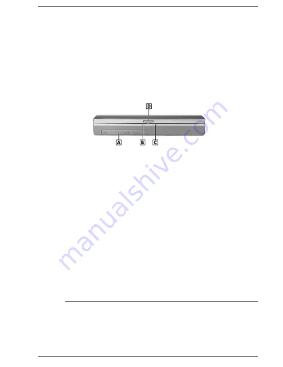
Front Features
The front features of your NEC Versa are described after the following the figure.
Front features
A – NEC VersaBay III
C – Battery Charging LED
B – Power Status LED
D – LCD Lid Latch
!
NEC VersaBay III™ — A 24X CD-ROM drive, a SuperDisk drive, a 6X DVD-ROM
drive, or a CD read/write drive comes installed in the NEC VersaBay III on the front of
your system.
The VersaBay III lets you add options, including an optional second Li-Ion battery, or
an additional hard disk drive.
!
Power Status LED — lights green when the system is under AC power. When the
system is under battery power, this LED lights to indicate the following:
Lights green when the system power is on.
Blinks green when the system is in Suspend (Windows 95/NT) or Standby
(Windows 98) mode.
Lights yellow (blinks when in Windows 95/NT Suspend mode or Windows 98
Standby mode) to indicate that battery power is at 8% capacity or less.
Lights amber (blinks when in Windows 95/NT Suspend mode or Windows 98
Standby mode) to indicate that battery power is at 3% capacity or less.
Note
When both the primary and a secondary battery are installed, the power status LED
indicates the total (primary plus secondary) battery status.
Summary of Contents for Versa LXi
Page 1: ...NEC Versa Notebook Computer NEC VERSA LXI S E R V I C E A N D R E F E R E N C E M A N U A L...
Page 80: ...4 System Board Layout LED Status Board Audio Board Connector Board Main Board...
Page 83: ...5 Illustrated Parts Breakdown Illustrated Parts Breakdown Parts List...
Page 84: ...5 2 Illustrated Parts Breakdown Illustrated Parts Breakdown...
Page 91: ...7 Troubleshooting Quick Troubleshooting Helpful Questions...
Page 99: ...9 Specifications System Components Connector Locations Memory Map Interrupt Controllers...


