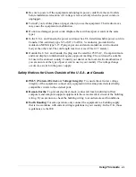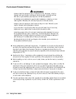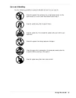
Be sure to power off the equipment and unplug its power cords from the wall outlets
before installation/relocation. All voltage is removed only when the power cords are
unplugged.
Turn off your cellular phone or pager when you use the equipment. Their radio waves
may cause the equipment to malfunction.
Do not use damaged power cords. (Replace them with new power cords of the same
type.)
In the U.S.A. and Canada, the power cord must be a UL-listed detachable power cord (in
Canada, CSA-certified), type ST or SJT, 16 AWG, 3-conductor, provided with a
molded-on NEMA type 5-15 P plug cap at one end and a molded-on cord connector
body at the other end. The cord length must not exceed 9 feet (2.7 meters).
Outside the U.S.A. and Canada, the plug must be rated for 250 VAC, 10 amp minimum,
and must display an international agency approval marking. The cord must be suitable
for use in the end-user country. Consult your dealer or the local electrical authorities if
you are unsure of the type of power cord to use in your country. The voltage change
occurs via a switch in the power supply.
Safety Notices for Users Outside of the U.S.A. and Canada
PELV (Protected Extra-Low Voltage) Integrity:
To ensure the extra-low voltage
integrity of the equipment, connect only equipment with mains-protected electrically-
compatible circuits to the external ports.
Remote Earths:
To prevent electrical shock, connect all local (individual office)
computers and computer support equipment to the same electrical circuit of the building
wiring. If you are unsure, check the building wiring to avoid remote earth conditions.
Earth Bonding:
For safe operation, only connect the equipment to a building supply
that is in accordance with current wiring regulations in your country. In the U.K., those
regulations are the IEE.
Using This Guide xi
Summary of Contents for VERSA S1300 Series
Page 1: ... U s e r s G u i d e NEC Storage S1300 ...
Page 2: ......
Page 4: ......
Page 8: ...vi Contents ...
Page 18: ...xvi Using This Guide ...
Page 19: ...1 System Overview Overview System Chassis System Features ...
Page 54: ...A B Figure 2 3 Installing the Rack Mounting Kit 2 6 Setting Up the System ...
Page 73: ...3 Upgrading the System Overview Adding Hard Disk Drives Adding Disk Enclosures ...
Page 86: ...3 14 Upgrading the System ...
Page 114: ...A 8 Appendix ...
Page 117: ...xx ...
Page 118: ... ...


