Rear Panel
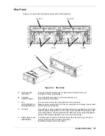
Figure 1-4 shows the rear panel connectors and indicators.
B (CONT0)
B (CONT1)
D C A (PS1)
A (PS0)
C
E
Figure 1-4 Rear View
A
Power supplies
(PS1/PS0)
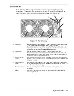
The power supplies are intended to supply power to the disk array unit.
See
System Power
in this chapter.
B
Controller
(CONT1/CONT0)
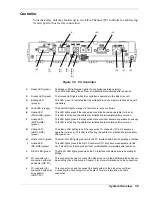
The controller board is used to control the disk array unit.
See
Controller
in this chapter.
C Fan
(FAN1-[0]/FAN1-[1]/
FAN0-[0]/FAN0-[1])
The unit comes with four fan units that allow it to cool properly.
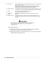
When the power switch is set to ON, the four cooling fans are rotating. Always check
that the vents are not blocked.
D
LAN card
The LAN card is used to write the cache data remaining in the disk array unit into the
disk drive before turning off the unit. The LAN card is provided for changing the disk
array configuration or monitoring failure of the disk array unit by using management
software "NEC Storage Manager". See
LAN Card
in this chapter.
E
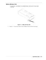
Battery backup units
(BBU1/BBU0)
The battery backup units are installed to protect the data remaining in the cache
memory at the occurrence of power interruption.
See
Battery Backup Units
in this chapter.
System Overview 1-5
Summary of Contents for VERSA S1300 Series
Page 1: ... U s e r s G u i d e NEC Storage S1300 ...
Page 2: ......
Page 4: ......
Page 8: ...vi Contents ...
Page 18: ...xvi Using This Guide ...
Page 19: ...1 System Overview Overview System Chassis System Features ...
Page 54: ...A B Figure 2 3 Installing the Rack Mounting Kit 2 6 Setting Up the System ...
Page 73: ...3 Upgrading the System Overview Adding Hard Disk Drives Adding Disk Enclosures ...
Page 86: ...3 14 Upgrading the System ...
Page 114: ...A 8 Appendix ...
Page 117: ...xx ...
Page 118: ... ...

