LAN Card
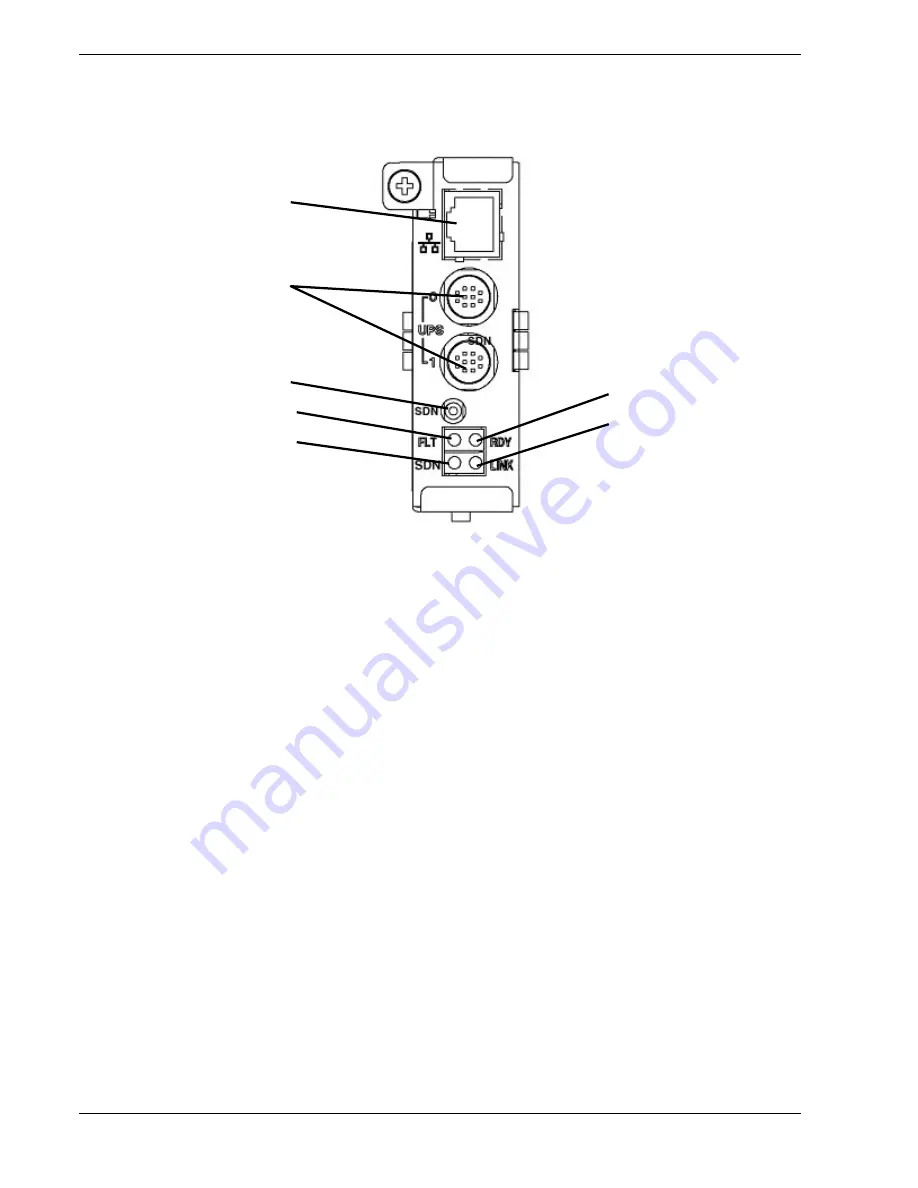
The unit incorporates a hot-swappable network interface controller.
A
B
C
G
D
F
E
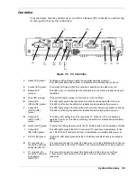
Figure 1-8 LAN Card
A
Ethernet connector
The Ethernet connector is used to connect to the Ethernet (10/100BASE-T) network for
remote maintenance or for using the disk array unit management software.
B
UPS connector
(UPS0/UPS1
connector)
This connector is used to connect the unit to a UPS.
In this configuration, the system can continue operating in stable state even if an
unexpected power failure or momentary AC power failure occurs.
C Shut Down switch
(push switch)
Use this switch to turn off the disk array unit.
Turning on this switch starts writing the cache data remaining in the cache memory of
the disk array unit to the disk drive.
For more information, see
Powering Off the Disk array Unit
in Chapter 2.
D
Fault LED
(FLT LED) (orange)
The Fault LED lights orange if a fault occurs in the LAN card.
In normal operation, the LED is off.
The Fault LED flashes when an error occurs while writing the data remaining in the
cache memory to the disk drive with the Shut Down switch being ON.
For more information, see
Powering Off the Disk Array Unit
in Chapter 2.
E Shut
Down
LED
(SDN LED) (green)
The Shut Down LED goes off while the LAN card operates normally.
The LED flashes green while writing the data remaining in the cache memory of the
disk array unit to the disk drive.
The LED lights when the cache data is completely written to the disk drive and the disk
array unit is ready to power off.
For more information, see
Powering Off the Disk Array Unit
in Chapter 2.
F Link
LED
(LNK LED) (green)
The Link LED lights green when transmission/reception of data starts on the Ethernet
network.
G Ready
LED
(RDY LED) (green)
The Ready LED lights green while the LAN card operates normally.
1-12 System
Overview
Summary of Contents for VERSA S1300 Series
Page 1: ... U s e r s G u i d e NEC Storage S1300 ...
Page 2: ......
Page 4: ......
Page 8: ...vi Contents ...
Page 18: ...xvi Using This Guide ...
Page 19: ...1 System Overview Overview System Chassis System Features ...
Page 54: ...A B Figure 2 3 Installing the Rack Mounting Kit 2 6 Setting Up the System ...
Page 73: ...3 Upgrading the System Overview Adding Hard Disk Drives Adding Disk Enclosures ...
Page 86: ...3 14 Upgrading the System ...
Page 114: ...A 8 Appendix ...
Page 117: ...xx ...
Page 118: ... ...

