Disassembly and Reassembly 3-17
Connector Board
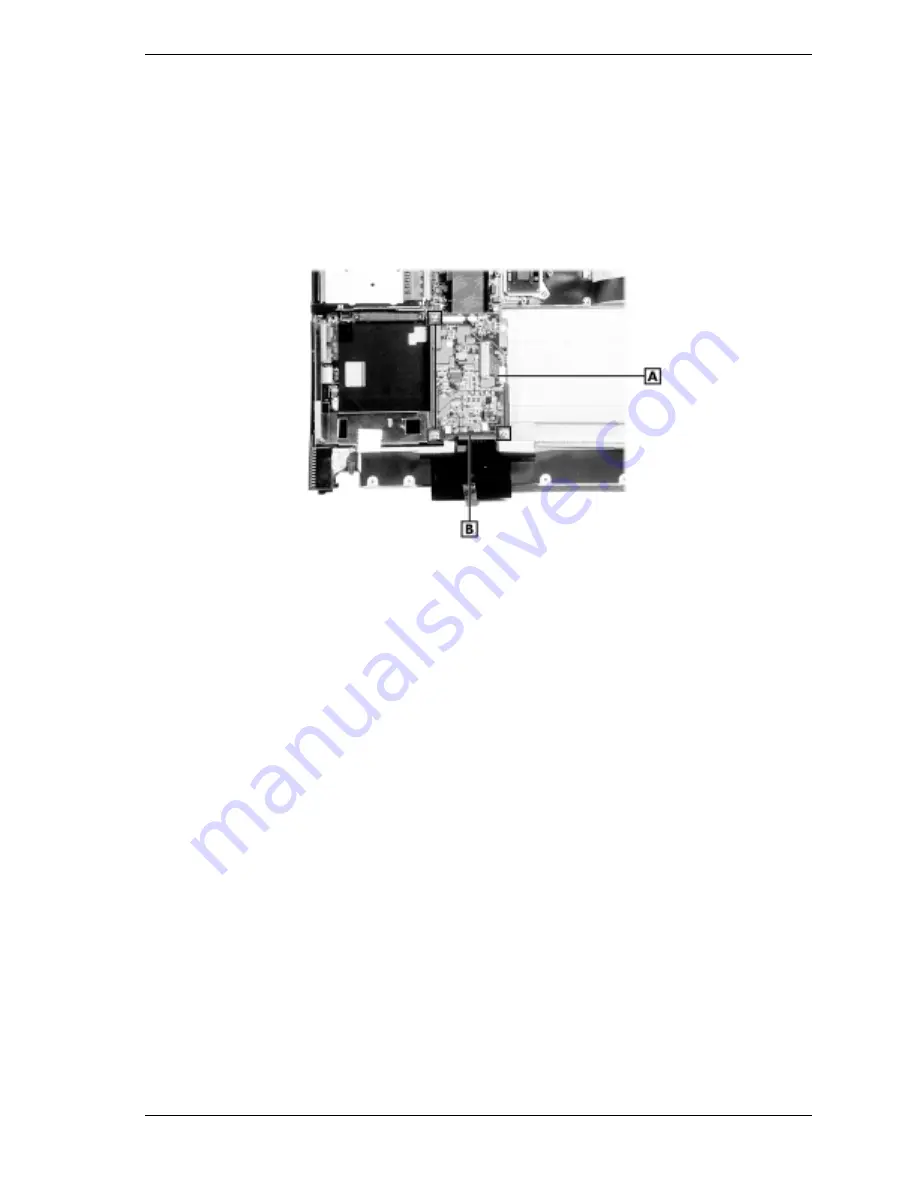
Remove the connector board as follows.
1.
Remove the keyboard, heatplate, top cover, bridge battery, and CMOS battery.
2.
Locate and remove the three screws securing the connector board.
Removing the connector board screws
A
– Connector Board
B
– Screws
3.
Lift the connector board up and away from the main board connectors.
4.
Detach the brackets to the left and right of the connector board site.
Summary of Contents for VERSA SXI
Page 1: ...NEC VERSA SXI SERIES S E R V I C E A N D R E F E R E N C E M A N U A L...
Page 65: ...4 System Board Layout Connector Board Main Board...
Page 68: ...5 Illustrated Parts Breakdown Illustrated Parts Breakdown Parts List...
Page 69: ...5 2 Illustrated Parts Breakdown Illustrated Parts Breakdown...
Page 75: ...7 Troubleshooting Quick Troubleshooting Helpful Questions...
Page 83: ...9 Specifications System Components Connector Locations Memory Map Interrupt Controllers...


