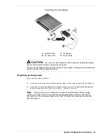
2-16
System Configuration and Setup
Setting the DIP Switch
Several system settings, including BIOS Flash, are set through a six-position DIP switch located
on the bottom of the notebook, under the memory bay cover. The following list identifies each
switch, its default setting, and its function. Procedures for setting the switches follow the list.
Switch 1 — Password override, default setting is OFF. If the password is forgotten, change
the switch setting to ON and the current password is erased.
Switch 2 — Keyboard select; default setting is ON for U.S. 85 key keyboard and OFF for
European keyboard.
Switch 3 — Not assigned; default setting is OFF.
Switch 4 — Keyboard select 2; default setting is ON for US and OFF for European
keyboards.
Switch 5 — Reserved for factory use; default setting is ON. Off is for BIOS Flash.
Switch 6 — Logo select; default setting is OFF.
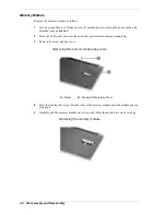
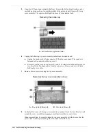
Use these steps to access the DIP switch in the memory bay and to set a switch.
1.
Power off the system and disconnect any peripheral devices.
Electrostatic discharge (ESD) can damage hard drives, boards,
processor, and other system components. Before opening the system and handling system
components, attach an antistatic wrist strap to your wrist and to chassis ground (any unpainted
metal surface on the system) to avoid ESD damage.
Hold a board only by its edges. If removing a board, place it component-side up on a grounded,
static-free surface or in a static-free wrapper. If installing a new board, do not remove it from its
protective wrapper until you are ready to install it.
2.
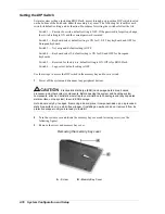
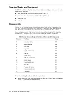
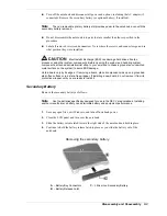
Turn the system over and locate the memory bay cover and fastening screw (see the
following figure).
3.
Remove the screw and memory bay cover.
Removing the memory bay cover
A
– Screw
B
–Memory Bay Cover
Summary of Contents for VERSA ULTRALITE
Page 42: ...3 Disassembly and Reassembly Required Tools and Equipment Disassembly Reassembly...
Page 58: ...5 Illustrated Parts Breakdown Illustrated Parts Breakdown Parts List...
Page 65: ...7 Troubleshooting Problem Checklist Startup Problems Diagnostics...
Page 73: ...8 NEC Computers Information Services Service and Support Functions Technical Support...
Page 76: ...9 Specifications System Components Memory Map Interrupt Controllers...


