Disassembly and Reassembly 3-13
LCD Panel
Remove the LCD panel as follows.
1.
Save any open files, exit Windows, turn off notebook power, close the LCD panel, unplug
the power cable, and disconnect any peripheral devices.
2.
On the back of the notebook, remove the adhesive backed foot and screw from each side of
the battery bay. The two screws partially secure the LCD panel to the base.
3.
Remove the secondary battery, hard drive, keyboard, top cover assembly, and main board.
4.
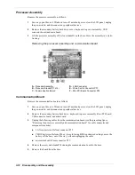
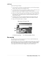
Remove the screw and cable clamp securing the LCD panel cable in place on the base (see
the preceding figure “Removing the processor assembly and communication board” for
clamp and cable locations).
5.
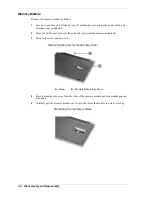
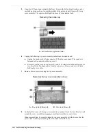
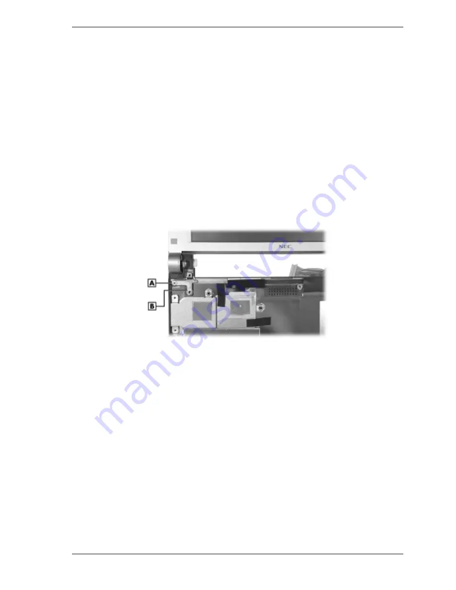
On each side, remove the screw securing the LCD panel hinge bracket to the base (the
following figure shows the left side hinge bracket and screw, the right side is similar).
6.
Remove the LCD panel and place in a safe place.
Removing the LCD panel screw
A
– Bracket Screw (left side)
B
– LCD Panel Hinge Bracket (left side)
Reassembly
Reassembly is the reverse of the disassembly process. Use care to ensure that all cables and
screws are returned to their correct positions.
Check that the power switch on the side of the notebook slides smoothly and does not bind. If it
does not slide smoothly, remove the top cover assembly (see “Top Cover Assembly” earlier in
this section for removal procedures). Reseat the top cover assembly, ensuring that the power
switch is against the side of the base while snapping the top cover assembly in place.
Summary of Contents for VERSA ULTRALITE
Page 42: ...3 Disassembly and Reassembly Required Tools and Equipment Disassembly Reassembly...
Page 58: ...5 Illustrated Parts Breakdown Illustrated Parts Breakdown Parts List...
Page 65: ...7 Troubleshooting Problem Checklist Startup Problems Diagnostics...
Page 73: ...8 NEC Computers Information Services Service and Support Functions Technical Support...
Page 76: ...9 Specifications System Components Memory Map Interrupt Controllers...

