background image

Configure Incoming Calls 


18 


     XN120 Voice Over IP Card Guide 

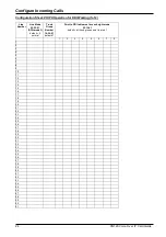
Configuration Sheet: Normal (Non-DDI) Operation 


Incoming Ring Group Target 22-05-01  

default = all trunks point to IRG 1 

Line 

Number 

Line Mode 

22-02-01 

default = 0 

normal 

1 2 3 4 5 6 7 8 

Members of the IRG 

Default = telephone 200 


10 


11 


12 


13 


14 


15 


16 


17 


18 


19 


20 


21 


22 


23 


24 


25 


26 


27 


28 


29 


30 


31 


32 


33 


34 


35 


36 


37 


38 


39 


40 


41 


42 


43 


44 


45 


46 


47 


48 


49 


50 


51 


Summary of Contents for XN120 Vision

Page 1: ...supplied for future reference Regulatory Notice Refer to the Getting Started Guide 991409 5 supplied with the XN120 Main Unit for the Declaration of Conformity related to the product Warning This is...

Page 2: ...IP Addresses 10 10 Test IP Connectivity 12 11 Configure SIP Trunks 14 12 Configure Incoming Calls 17 Non DDI Operation 17 DDI Operation 19 Set the VOIPU lines as DDI Mode 20 Assign each VOIPU line to...

Page 3: ...y recommended that you consult the NEC Infrontia Voice Over IP Reference Manual 991451 5 before attempting this XN120 VOIPU Cards Available Each XN120 VOIPU card has 4 Digital Signal Processors DSP on...

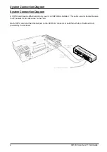
Page 4: ...port only even if a VOIPUDB is installed This port is used to transmit receive the IP packets for all calls active on the card Each VOIPU card and the Ethernet port on the EXIFU A1 connects to an Ethe...

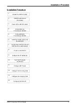
Page 5: ...EXIFU A1 if not already installed 5 Fit the 2OPBOX if not already installed 6 Install the VOIPU card s into the 2OPBOX 7 Connect the VOIPU cards and EXIFU A to the data network 8 Power on the XN120 9...

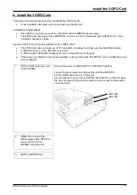
Page 6: ...rom its packaging and locate the black 40 pin connector on the PCB CN11 on the VOIPU and CN6 on the Daughterboard Gently place the daughterboard onto the VOIPU so that the 4 plastic legs locate into t...

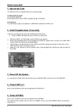
Page 7: ...the XN120 unit s A VOIPU will use 4 of the XN120 s trunk ports A VOIPU with a VOIPUDB installed will use 8 of the XN120 s trunk ports If there are not sufficient trunks ports available on the system...

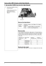
Page 8: ...Cable CAT5 or better Straight Cross Ethernet Cable The connections of the Ethernet cable depend on the device that you connect When connecting to an Ethernet hub you would normally use a straight cabl...

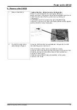
Page 9: ...the MOH Page connector on the main unit refer to the Getting Started Guide supplied with the XN120 for further information 2 The VOIPU card s will be automatically configured Check the VOIPU card s ha...

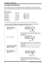
Page 10: ...bnet Mask for the XN120 this must be specified by the Network Administrator responsible for the customers LAN 1 Program 10 12 01 Enter the IP Address of the XN120 system Enter the Subnet Mask You must...

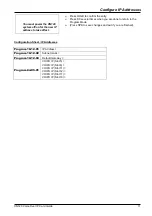
Page 11: ...Press DC several times when you are done to return to the Program Mode Press SPK to save changes and exit if you are finished Configuration Sheet IP Addresses Program 10 12 01 IP Address Program 10 12...

Page 12: ...net network you will notice that this LED is lit almost constantly Test 2 PING If there is a layer 1 connection and the IP details are correct it should be possible to ping the VOIPU card and the EXIF...

Page 13: ...s TTL 30 Ping statistics for 172 16 0 10 Packets Sent 4 Received 4 Lost 0 0 loss Approximate round trip times in milli seconds Minimum 0ms Maximum 1ms Average 0ms b Unsuccessful No reply is received t...

Page 14: ...P Parameters The XN120 has several system wide settings that have to be programmed to enable SIP to work These items are located in Program 10 28 Setting CODEC Options The XN120 uses a CODEC Coder Dec...

Page 15: ...is field does not have to be a valid domain name but it is recommended that the same domain name is used for all XN120 systems within the SIP network example mysipnetwork co uk Host Name This identifi...

Page 16: ...Priority This is the CODEC that will be used for SIP Trunk Calls 0 G711 1 G723 2 G729 Default Setting G 711 Enter the CODEC Type to use for SIP Trunk calls Press DC several times when you are done to...

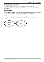
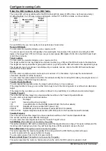
Page 17: ...digits then the BRI lines can be routed in exactly the same way that you would route an analogue trunk Refer to the XN120 Getting Started Guide for more detail In brief Route each VOIPU line to an In...

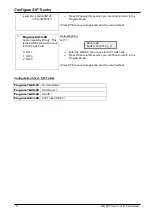
Page 18: ...g Ring Group Target 22 05 01 default all trunks point to IRG 1 Line Number Line Mode 22 02 01 default 0 normal 1 2 3 4 5 6 7 8 Members of the IRG Default telephone 200 1 2 3 4 5 6 7 8 9 10 11 12 13 14...

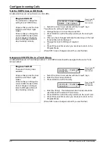
Page 19: ...fied In brief Set each VOIPU line as DDI mode in Program 22 02 01 ensure you do this for all night modes You then place the lines into Trunk Groups in Program 14 05 01 route each Trunk Group to an are...

Page 20: ...and exit if you are finished Assign each VOIPU line to a Trunk Group At default all lines are in Trunk Group number 1 All VOIPU trunks should be assigned to the same Trunk Group number Program 14 05...

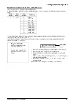
Page 21: ...each night mode in use by the customer For example during day mode the main DDI number routes to reception but in night mode the same DDI number must route to voice mail Program 22 13 01 Point the tru...

Page 22: ...u can specify the operation when the target number is busy or ring no answer If the target number is busy you can either return busy tone to the incoming caller or overflow to an alternative target If...

Page 23: ...entry number 1 2000 with the Vol p q keys Enter the DDI receive digits Press HOLD to confirm the entry and step to the next option Enter the target number Press HOLD to confirm the entry and step to...

Page 24: ...Mode 22 02 01 DDI mode 3 default 0 normal Trunk Group Number 14 05 01 default 1 Point to DDI table area for each night mode 22 13 01 default all trunk groups point to area 1 1 2 3 4 5 6 7 8 1 2 3 4 5...

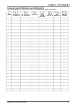
Page 25: ...more than 50 DDI entries are required DDI entry number Receive digits 22 11 01 default entries 1 99 have 00 99 Target 22 11 02 default entries 1 99 have 200 299 Name 22 11 03 default blank Transfer O...

Page 26: ...mber 1 If you have changed the Trunk Group number of the VOIPU lines in Program 14 05 01 you will also need to include the new trunk group number within the route used when 9 is dialed You can assign...

Page 27: ...network there needs to be a method of translating dialed numbers to IP addresses these cannot be automatically determined as in the previous example The XN120 has a dialing table that is referred to...

Page 28: ...n to send calls beginning with 01 to Select the correct table entry number 1 1000 with the Vol p q keys Press 1 to enable this table entry Press HOLD to confirm the entry and step to the next option E...

Page 29: ...re entries are required up to 1000 entries can be used System Number System Interconnection PRG10 23 01 Yes No Destination IP Address PRG10 23 02 Call Control PRG10 23 03 Dial Number PRG10 23 02 1 2 3...

Page 30: ...insertion of the prefix digits 0 for national calls and 00 for international calls This is enabled by Program 20 19 03 set this option to 1 to enable the insertion of the 0 or 00 prefix digits If the...

Page 31: ...001 010 IP Address of remote system 10 23 04 Sys 1 3 2 Digits to associate with remote system 10 28 01 xn120 co uk SIP Domain Name 10 28 02 systema systemb SIP Host Name 10 28 04 200 300 UserID for s...

Page 32: ...the system phone to select the program item and change its value etc The LCD display will show the current program item the editing point is shown by a flashing curser SPK Save changes and exit config...

Page 33: ...o step on to the next if you did not make any changes to the entry Exiting Configuration Mode When you exit configuration mode your changes will be saved into the battery backed memory Until you exit...

Page 34: ...Integrated Services Digital Network IETF Internet Engineering Task Force The IETF is an international community of network designers operators vendors and researchers whose purpose is to coordinate th...

Reviews: