P61 firmware
© Nedap IDEAS, P.O. Box 103, NL-7140 AC GROENLO
Page 4 of 18
2 DIP SWITCH SETTINGS
The TRANS-IT
®
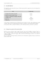
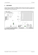
(PS-270) has 8 DIP-switches, which are used by the P61 firmware as described in the
table below. Refer to appendix A when locating the DIP-switches.
VALUE
8
7
6
5
4
3
2
1
Use default antenna
ON
x
x
x
x
x
x
x
Microwave and inductive antenna
OFF
x
x
x
x
x
x
x
Framelength 128 bit
x
ON
x
x
x
x
x
x
Framelength 64 bit
x
OFF
x
x
x
x
x
x
Manchester decoding disabled
x
x
ON
x
x
x
x
x
Manchester decoding enabled
x
x
OFF
x
x
x
x
x
Baudrate 9600
x
x
x
ON
ON
x
x
x
Baudrate 1200
x
x
x
ON
OFF
x
x
x
Baudrate 19200
x
x
x
OFF
ON
x
x
x
Baudrate 38400
x
x
x
OFF
OFF
x
x
x
Data format 7/even/1
x
x
x
x
x
ON
x
x
Data format 8/none/1
x
x
x
x
x
OFF
x
x
Table 1: DIP-switch settings
Note1:
Set DIP-switch 8 only to OFF when using a TRANS-IT
®
reader with an inductive (120kHz) antenna connected.
The P61 firmware then tries to identify transponders on both antennas (microwave and inductive). When on
one antenna a valid transponder is identified it sticks to that antenna source and does not identify anymore on
the other antenna. So, when a vehicle is identified with the microwave antenna and this vehicle stays in front of
the TRANS-IT
®
, nobody is identified at the inductive antenna.
When identifying vehicles at high speed it is recommended to keep DIP-switch 8 in ON position.
Note2:
Set DIP-switch 7 to OFF when no combi-booster or EF-coded transponders are to be identified. This
increases the detection speed. DIP-switch 7 is only read during a startup.
Note3:
Set DIP-switch 6 to OFF when manchester encoded transponders (e.g. EM Marin 400x) are to be identified.
3 LED INDICATORS
A number of LED's are used by the P61 firmware to indicate the current status. The table below describes
the function of each
LED
. Refer to appendix A when locating the LED's.
LED
Description
STS
Status
LED
.
Indicates that the power is on and the processor is running. The
LED
continuously
blinks like the system's heartbeat.
ID
Identification
LED
.
This green
LED
starts to blink fast when a valid transponder is identified.
The
LED
stays off when no (valid) transponder is identified.
UL
Unlock
LED
.
The unlock
LED
is normally off and goes on when a valid transponder is identified. The
LED
is turned off when no transponder is identified anymore and the relay-hold-time
has elapsed. This
LED
can be connected to a Reflex or DC130 antenna.
There is also a relay contact present which has the same function.
NA
Lock
LED
.
Red
LED
indicating system standby. This
LED
is normally on and goes off when the
unlock
LED
goes on. This
LED
can be connected to a Reflex of DC130 antenna.
INP /
DOOR
Input status
LED
This red
LED
is on when the input contact is closed. The input is not used in the P61
firmware.
Table 2: LED indicators

