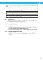
background image

NCF

EN

22

4.4.3 

Storage in a warehouse

CAUTION! 

Risk of equipment damage. 

Close intake and exit openings during storage.

Should it be necessary to store the fan in a warehouse, it must be protected from 

atmospheric conditions, humidity, dust and any harmful substances present in the air.
It is recommend to periodically check that the fan is in a good condition and turn the 

impeller manually approximately once a month to prevent the deformation of its bearings.

4.5 

Mounting

NOTE! 

The support surface must be sufficiently rigid to withstand normal fan vibrations, 

and must not be subject to phenomena of structural resonance.

NOTE! 

If the fan is mounted on a structure raised above floor level, the vibration 

characteristics of this structure must be verified.

Special foundations are not necessary for positioning the fan. A well-levelled concrete 

support surface is sufficient, suitable to withstand the weight load of the fan and the 

dynamic stresses generated by its normal operation.
During installation, the user and/or installer must take the necessary measures to reduce 

vibrations from the overall system (fan and ducts).
The support surface must be flat and horizontal, to prevent the bending and misalignment 

of supports. If necessary, suitable metal spacers must be placed between the fan base and 

the support surface to ensure perfect adherence. Use the fixing points provided, ensuring 

that the tightening of nuts and bolts does not deform fan structures.
Ducting connected to the fan must be supported separately, and must be coaxial with 

respect to the intake and exit openings, so as to prevent deformation caused by the 

tightening of nuts and bolts.

4.5.1 

Outdoor installation

CAUTION! 

Risk of equipment damage. 

• 

An IP55 motor will not be water tight in outdoor operating conditions. The application 

where the motor is used, mounting position and actual exposure to external factors 

must be taken into account. 

• 

Make sure there are draining holes in the fan casings for fans used in outdoor 

installations.

• 

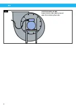
Leave a bend on the cable before the motor so that water can run down and off of the 

cable. See figure 11.

If the fan is to be used outdoors or under other circumstances where moisture and 

condensation can be present the motor must be protected by a suitable cover.
Make sure to have a draining hole in the lowest level of the fan casing. Drill a hole 

(approximately Ø 5 mm). Then treat the hole with an anticorrosive agent. 

4.5.2 

Minimum distances between components 

WARNING!

The access of personnel, even if qualified, to the intake area of fans capable of developing, 

with zero flow, a negative pressure greater than 5000 Pa, must be prohibited.

Summary of Contents for 14550128

Page 1: ...Central Fan NCF 2130187 01 2018 12 07 Original instruction manual EN INSTRUCTION MANUAL Instruction manual ...

Page 2: ...NCF 2 Declaration of conformity 3 Figures 4 English 9 ...

Page 3: ...Directives 2006 42 EC 2014 30 EU 2009 125 CE Reg CE 327 2011 The name and signature at the end of this document is the person responsible for both the declaration of conformity and the technical file English EN 14550128 14550228 14550328 14550428 14550528 14550628 14550728 14550828 14550928 14551028 14551128 14551228 14551328 14551428 14551528 14552128 14552228 14552328 14552428 14552528 14552628 ...

Page 4: ...n 230 V Y connection 460 V connection 460 V U1 V1 V5 U5 W1 W5 W2 U2 V2 U1 V1 W1 L1 L2 L3 U1 V1 W1 W2 U2 U5 W5 V2 V5 W2 U2 V2 U1 V1 W1 L1 L2 L3 U1 V1 W1 W2 U2 U5 W5 V2 V5 W2 U2 V2 U1 V1 W1 L1 L2 L3 U1 V1 W1 U5 V5 U2 W2 V2 W5 Figures 1 2 Delta connection 3 Star connection 4 ...

Page 5: ...ion RD RD0 Standard RD90 RD30 RD60 RD120 RD150 RD270 RD300 RD330 OUTLET DIRECTIONS Can be positioned after order Clockwise rotation RD RD0 Standard RD45 RD90 RD135 RD270 RD315 Outlet directions for all NCF fans except NCF 30 15 Outlet directions only for NCF 30 15 6 ...

Page 6: ...NCF 6 Example of lifting NCF fans 7 Minimum installation distances with inlet duct 8 ...

Page 7: ...NCF 7 10 mm Max 40 mm Max 10 Max Theoretical Parallel misalignment Axial compression Angular misalignment 9 Minimum installation distances with open inlet 10 ...

Page 8: ...NCF 8 OUTDOOR INSTALLATIONS Leave a bend on the cable to prevent water from entering the motor 11 ...

Page 9: ...rd fan outlet position for NCF fans 19 4 3 Installation types 20 4 4 Transport 21 4 4 1 Transport and lifting 21 4 4 2 Lifting NCF fans 21 4 4 3 Storage in a warehouse 22 4 5 Mounting 22 4 5 1 Outdoor installation 22 4 5 2 Minimum distances between components 22 4 5 3 Electrical connections 23 4 5 4 Motor connections 23 4 6 Connection to ducts 23 4 7 Checks to be made before and after starting 23 ...

Page 10: ... damaged or missing parts when the product is delivered notify the carrier and the local Nederman representative immediately 2 Safety This document contains important information that is presented either as a warning caution or note WARNING Risk of personal injury Warnings indicate a potential hazard to the health and safety of personnel and how that hazard may be avoided CAUTION Risk of equipment...

Page 11: ... the fan mouth and ejected at high speed from the fan intake or exit Structural defects of fan components Contact with fan surfaces at dangerous temperatures for example below 20 C or higher than 50 C When working with hot fluids there may be losses of jets of hot fluid from the transmission shaft hole that may cause burns or scalds The potential harmfulness of the fluid being moved or the presenc...

Page 12: ...he fan is only a single component Avoid working at speeds coinciding with structural resonance frequencies and if this is not possible modify some variable that can change the resonance frequency of the system for example by using vibration dampers of a different type Vibrations are the main factor affecting the operational life and safety of fans and for this reason it is essential to accurately ...

Page 13: ...ns overspeed conditions may be created due to Errors in the control logic system Short circuits on monitoring components Driver or inverter malfunctions Mechanical breakage of components and in particular on encoder During normal operation conditions of overspeed attributable to the drive system or motor may occur in particular if the fan is supplied with shaft only or with motor without drive sys...

Page 14: ...s of restricted environments or if the fan is installed against walls the effect of reverberation and resonance on structures walls and ceiling is exponential The definition of the risks to workers of exposure to noise is not the responsibility of Nederman which limits itself to indications of values levels of uncertainty standards or criteria used for noise emission measurements As envisaged by a...

Page 15: ...n above ground may arise with possible injury to persons and or damage to things 3 3 Life cycle of fan The reliability of all components is guaranteed if they are properly maintained and if Nederman original parts and accessories are used For safety reasons guards in electrowelded wire must be replaced every 2 to 3 years If the fan is used at constant speed for two work shifts every day equivalent...

Page 16: ... 15 NCF 120 25 NCF 160 25 Capacity m3 h 535 4180 700 4315 830 6000 910 6550 800 5600 1600 8540 2600 13980 2340 11650 2650 17140 Total pressure Pa 1970 575 2890 950 2540 870 3640 1320 4540 1570 3170 1020 3590 1170 5260 1700 5060 1870 Motor power kW 2 2 3 0 4 0 5 5 5 5 7 5 11 15 18 5 Speed r min 3500 3515 3535 3510 3520 3550 3540 3550 3560 Voltage V Current A 208 8 6 208 11 5 208 15 1 208 18 7 208 1...

Page 17: ...rrent A 380 8 2 380 10 8 380 10 8 380 14 5 380 27 9 380 34 Phase 3 phase 3 phase 3 phase 3 phase 3 phase 3 phase Starting current 6 7 x rated current 6 7 x rated current 6 7 x rated current 6 7 x rated current 6 7 x rated current 6 7 x rated current Protection IP 55 IP 55 IP 55 IP 55 IP 55 IP 55 Weight kg 105 110 112 150 232 292 Working temperature C Maximum 60 Maximum 60 Maximum 60 Maximum 60 Max...

Page 18: ...aximum 140 Ambient temperature F 22 to 104 22 to 104 22 to 104 22 to 104 22 to 104 22 to 104 22 to 104 22 to 104 22 to 104 Sound power level Lw A 3dB 94dB A 103dB A 97dB A 106dB A 106dB A 98dB A 104dB A 107dB A 103dB A Sound pressure level Lp A 3dB 80dB A 89dB A 82dB A 83dB A 86dB A 83dB A 89dB A 92dB A 90dB A Reference standards ISO 3744 ISO 3746 ISO 13347 Installation Type D ducted inlet ducted ...

Page 19: ...conservation of the minimum access spaces requested for maintenance operations must be verified 4 1 Delivery check If there are any damaged or missing parts when the product is delivered notify the carrier and the local Nederman representative immediately 4 2 General information 4 2 1 Fan orientation See Figure 6 NCF fans can be supplied with 9 different orientations except for the NCF 30 15 that ...

Page 20: ... supply There are four possible installation types in compliance with UNI 10615 specifications Type A open intake and outlet Type B open intake and outlet connected to a pipe Type C intake connected to a pipe and open outlet Type D intake and outlet connected to a pipe Clearly AB Ph Nederman Co cannot be aware of which of these four installation types will be used by the user Therefore the install...

Page 21: ... best suited for both load and functionality CAUTION Risk of equipment damage The user assumes liability for the choice of the lifting equipment and ropes straps or chains considered to be most suitable both for the purpose and for their lifting capacity For lifting and movement do not use zones or points other than those marked by a symbol See Table 2 1 Explanation of sign and sticker symbols use...

Page 22: ...ts If necessary suitable metal spacers must be placed between the fan base and the support surface to ensure perfect adherence Use the fixing points provided ensuring that the tightening of nuts and bolts does not deform fan structures Ducting connected to the fan must be supported separately and must be coaxial with respect to the intake and exit openings so as to prevent deformation caused by th...

Page 23: ...on the terminal board The client must also install an electrical disconnecting device near the fan so that maintenance personnel can have direct control over the power supply to the fan All work performed on the electrical system must only be carried out with the fan at rest and electrically disconnected from the mains Before installing starting up ensure that the information on the identification...

Page 24: ...tion it is normal for the bearings to reach slightly higher temperatures as long as they later stabilise at a lower value In the event of overheating of the bearings contact the Nederman technical assistance department After 3 4 operating hours with the fan at rest and disconnected from the power supply check again that all bolts are correctly tightened and the bearing temperature 4 7 3 Visual che...

Page 25: ...ger warnings must be also maintained in perfect efficiency and in their correct position When troubleshooting any faults or malfunctions with fans take all the precautions described in this manual intended to prevent all and any kind of injury to persons or damage to things Remember to tighten all bolts nuts and fixing rings on all mechanical components that are adjusted or serviced following the ...

Page 26: ...n is operating CAUTION Risk of equipment damage Periodic cleaning and maintenance are essential to ensure correct fan operation and a longer operative life span of the fan A fan maintenance program must be drawn up and followed to prevent the mechanical failure or breakage due to wear or insufficient maintenance The fan must be disconnected and isolated from the electrical power supply during main...

Page 27: ...check instrument Criteria for acceptability Result Impeller blade thickness Dimension Caliper Reduction of thickness no greater than 10 in an area without wear or with paint undamaged Impeller thickness of impeller disk Dimension Caliper Reduction of thickness no greater than 10 in an area without wear or with paint undamaged Casing thickness of sides and sheeting Dimension Caliper or equivalent R...

Page 28: ...or more pieces secured together by bolts 6 3 3 Impeller Remove the nozzle and where possible the fan housing With single intake fans remove the screw together with the lock ring and use a suitably sized extractor We recommend setting up a support for the impeller before extracting it completely In any event this operation must always be carried out with great care avoiding any knocks that could al...

Page 29: ... of equipment damage Use only Nederman original spare parts and accessories Contact your nearest authorized distributor or Nederman for advice on technical service or if you require help with spare parts See also www nederman com Ordering spare parts When ordering spare parts always state the following Part number and control number see the product identification plate Detail number and name of th...

Page 30: ...tion speed too high Reduce rotation speed Resistance pressure of system lower than design value Check the resistance pressure value of the system Incorrect impeller rotation direction Check impeller rotation direction and orientation Pre rotation of air in opposite direction to fan rotation Check minimum installation distances paragraph 5 1 1 or correct orientation of intake with pre distributors ...

Page 31: ...NCF 31 EN ...

Page 32: ......

Page 33: ...www nederman com ...

Reviews: