


NCF
EN
28
6.3
Disassembly
WARNING!
Risk of personal injury!
All the disassembly and reassembly operations described below must only
be carried out by qualified and authorised personnel. For no reason whatsoever
must the operator or factory personnel carry out these operations.
CAUTION!
All the disassembly and reassembly work must be carried out with the following conditions:
•
You must be absolutely certain that the fan is completely stationary (impeller at rest);
disconnect the electrical power at the main panel with the switch, lock the switch with a
padlock and hand the key to the head of maintenance.
•
The working environment must be equipped with every tool necessary and must be free
of any hazards.
•
Every piece to be refitted must be thoroughly cleaned, degreased and lubricated as
necesasary before refitting.
6.3.1
Intake nozzles
Undo the nozzle securing nuts from the fan housing. Slide out the nozzle.
6.3.2
Housing
With all orientable fans, the housing is secured to the frame by bolts. Simply undo the
securing nuts at the frame plate. With non-orientable fans with single-piece housings, the
housing cannot be disassembled. The housing in certain fan types may be divided into two
or more pieces, secured together by bolts.
6.3.3
Impeller
Remove the nozzle and, where possible, the fan housing. With single intake fans: remove
the screw together with the lock-ring and use a suitably sized extractor. We recommend
setting up a support for the impeller before extracting it completely. In any event, this
operation must always be carried out with great care, avoiding any knocks that could alter
the balance of the impeller or deform it.
6.4
Flexible anti-vibration joints between the fan and ducting
Flexible joints located between the fan and exit and/or intake ducting must be checked
visually to ensure that they are undamaged and that no flexible components have become
detached. If these joints must be dismantled for maintenance of the system and/or the
fan, they must be reassembled taking the precautions indicated for the first assembly/
installation.
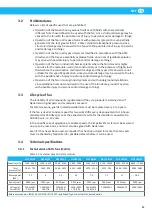
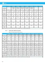
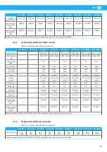
6.5
Technical enclosures
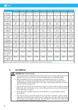
Tightening torques for nuts and bolts
The tightening torques M given in the table are applicable in the following conditions:
•
Hexagonal head UNI 5737 type screws, cylindrical head UNI 5931 and UNI 6107 type
screws, in normal conditions in which they are supplied.
•
Tightening torques must be applied slowly using a torque wrench.
While maintaining the same pre-load values, tightening torques must be modified as
described below in the following cases:
•
Increased by 5% for wide-head UNI 5712 screws.


