L-PAK 150, L-PAK 250
NOTE!
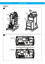
The exhaust air duct should be routed straight
and as short as possible. Pressure drop for com-
plete system shall be considered by the install-
ation designer or the user.
1
Incoming 3-phase power supply with PE cable.
2
Switch-disconnector according to standard.
3
Power cable to the unit.
4
Compressed air valve, size G1/4” or G1/2”.
5
Water and dirt-trap. Compressed air supply must
be clean and dry.
6
Compressed air supply, Ø 6 mm nylon hose.
7
Vacuum pipe from workstations.
8
Exhaust air duct Ø 100 mm. Ø 160 mm pipe is used
for lengths greater than 12 m.
9
Pilot signal cable (PS) from valves at workstations.
(AS-set required, accessory.) Strap terminals
13-14 when the pilot signal cable is not installed.
5 Initial Start-up
WARNING! Risk of personal injury
Never run the unit without an exhaust air duct.
An incorrectly installed/positioned exhaust air
duct can cause personal injury. The exhaust
air/exhaust air duct can reach high temperat-
ures.
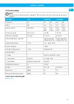
The L-PAK 150, L-PAK 250 with options is tested be-
fore delivery and all functions are checked.
5.1 Before starting for the first time
Before starting for the first time, check that:
• The switch-disconnector is installed.
• The unit room, if small, has ventilation openings.
See
• The plastic sack is in place in the collector bin. The
unit should not be used without a plastic sack!
• The pipework is connected to the dust collector in-
let.
• An exhaust air duct is attached to the outlet to lead
away hot exhaust air.
• The compressed air supply is permanently connec-
ted. Filter cleaning, idling and cooling do not func-
tion when there is no compressed air!
• Pilot signal cable installed (when the function auto-
matic start/stop is used).
• The terminals 13-14 in the start and control unit are
strapped when the system is not equipped with the
automatic start/stop function i.e. the pilot signal
cable is not routed to workstations.
5.2 Start-up
The expression “automatic start/stop” in the following
text means both automatic idling and automatic start/
stop.
NOTE!
The acoustic enclosure (accessory) should be
removed during initial start-up to check the dir-
ection of rotation. Check that there are no open
vacuum valves at the workplaces.
• See
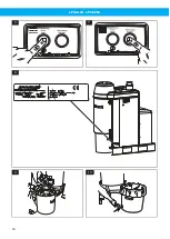
. Turn the switch-disconnector to posi-
tion 1.
• See
. Press the white push button on the
control panel until the white lamp lights. When the
automatic start/stop function is not used the unit
should start directly.
NOTE!
When the L-PAK 150, L-PAK 250 has the auto-
matic start/stop function enabled it should not
start directly except when a valve at a worksta-
tion is opened or when the button for Manual
start is pressed, see
• Check the direction of rotation with the arrow mark.
If these correspond then allow the starting proced-
ure to continue. Otherwise, stop the unit by press-
ing the button shown in
. Isolate the power
by using the switch-disconnector. Open the start
and control unit and change two of the incoming
phase conductors. Check the rotation again.
• Check that the unit, if it has automatic starting and
stopping, does not start immediately when the but-
ton marked in
is pressed. The lamp in the
push button should come on to indicate that the
starter is now in “Standby” mode and ready to re-
ceive the start signal from the pilot signal cable.
The unit should not start until you open a valve at
a workplace so that the microswitch makes, or you
press Manual start.
After approximately 30 seconds the unit switches to
idling (and filter cleaning). After 10 minutes the unit
should stop. If the unit starts without any valve being
opened this is an indication that the pilot signal cable
is closed at some point. Disconnect the cable from the
starter and use an ohmmeter across the leads in turn
until the fault has been located and remedied.
• Press the Manual Filter Cleaning button shown in
, and check whether the filter cleaning pro-
cedure starts. The valve is hidden under the en-
closure, but a distinct change in sound reveals the
function, this will be repeated 3 times for each filter
cleaning cycle.
• With the pipework fully sealed and all valves at
workstations closed, verify that the vacuum limiting
valve opens and admits air to limit the vacuum.
• Replace the cover on the start and control unit
when all controls have been carried out. Replace the
EN
21
Summary of Contents for 40051800
Page 8: ...L PAK 150 L PAK 250 Figures 1 2 8 ...
Page 9: ...L PAK 150 L PAK 250 3 4 5 9 ...
Page 10: ...L PAK 150 L PAK 250 6 7 8 9 10 10 ...
Page 11: ...L PAK 150 L PAK 250 11 12 13 14 11 ...
Page 178: ...www nederman com ...


