L-PAK 150, L-PAK 250
3.4 Main components
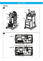
See
. The L-PAK 150, L-PAK 250 consists of
the following main components.
1
Start and control unit.
2
Control panel.
3
Outlet silencer.
4
Micro-filter housing.
5
Thermal switch.
6
High-pressure side channel fan, with pump char-
acteristic.
7
Filter cleaning device.
8
Dust collector.
9
Filter.
10 Collector bin with plastic sack. The unit should not
be used without a plastic sack!
11 Vacuum limiting valve.
12 Connection hose for pressure equalisation
between the collector bin and the inlet silencer.
13 Acoustic enclosure (accessory).
14 Top cover.
(The arrows indicate the air path, A = inlet B = outlet)
3.5 Start and control unit
See
. The start and control unit consists of the
following main components:
1
Transformer (TR1). The transformer has in-built
overcurrent protection on the secondary side.
2
Transformer primary fuses F2 & F3.
3
Overcurrent relay (motor protection) with manual
reset button (S1F).
4
Contactor L-PAK 150/Gradual start unit L-PAK
250.
5
PLC.
6
Terminals for 3-phase supply and grounding
cables.
7
Terminals 31 & 32 for 24 V DC accessory supply.
Fuse F5.
8
Terminals 13 & 14 for pilot signal cable (PS). Fuse
F4. Strap 13-14 if the pilot signal cable is not used.
9
Other terminals required by some accessories, all
24 V DC. See the connection diagram.
There is a white warning lamp that lights whenever
a fault occurs. This is a common alarm. The following
faults will cause the lamp to flash rapidly:
• The motor overload relay has tripped.
• The fan thermal switch has tripped.
• No compressed air supply. (The optional Com-
pressed Air Switch, CAS, must be installed.)
3.5.1 Y/D-start or gradual start
L-PAK 150 is direct started (contactor). L-PAK 250
starts gradually (gradual start equipment).
3.5.2 Automatic start/stop or continuous
operation
The functions automatic idling (DIR function) and
automatic starting and delayed stopping (SSR func-
tion) are always included in the start and control unit.
To make proper use of the facilities all vacuum valves
at workstations must be fitted with a microswitch (AS
set) connected to a pilot signal cable that runs to the
start and control unit.
3.5.3 Filter cleaning
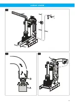
shows the principle for filter cleaning. A PLC
controls a solenoid valve (A) which in turn controls a
compressed air cylinder (B) with a valve disc. The prin-
ciple requires negative pressure in the dust collect-
or so that the “accumulated vacuum”, when the valve
opens, gives a short but powerful blast of reverse air
through all the filter which will dislodge the dust de-
posited on the outside of the filters, this will be re-
peated 3 times for each filter cleaning cycle.
This method works best in installations with automat-
ic vacuum valves at the workstations. Filter cleaning
occurs every time the L-PAK 150, L-PAK 250 switches
to idling on installations that utilise the functions of
automatic idling and automatic starting and stopping.
This filter cleaning arises in addition to filter cleaning
tripped by the filter cleaning function in the PLC.
3.6 Inlet
The dust collector is designed to keep the airspeed
in the lower part of the collector as low as possible.
Coarse dust falls directly into the collector bin.
Fine dust follows the airflow upwards and deposits
on the outer surfaces of the filter with surface filtra-
tion. The filter has a smooth surface on the outside
with fine pores, so that dust is separated directly onto
the surface without penetrating into the filter mater-
ial. This makes the filter easy to clean, gives a high de-
gree of separation and permits intense use, i.e. a large
flow of air in relation to the surface area.
The clean air leaves the collector through the top and
passes via the micro-filter housing into the side chan-
nel fan with an integrated motor.
The unit can be equipped with a micro-filter,
as an accessory.
3.7 Fan
The fan has a pump characteristic, i.e. the higher the
vacuum it creates the more power it draws from the
motor.
There is a vacuum limiting valve located close to the
fan inlet which opens when the vacuum becomes too
great,
. A weight (A) normally keeps the valve
cone (B) closed. At about - 20 kPa vacuum the cone
lifts as shown in the illustration, allowing air to flow
into the fan. This is how the vacuum level, power con-
sumption and temperature are controlled.
EN
19
Summary of Contents for 40051800
Page 8: ...L PAK 150 L PAK 250 Figures 1 2 8 ...
Page 9: ...L PAK 150 L PAK 250 3 4 5 9 ...
Page 10: ...L PAK 150 L PAK 250 6 7 8 9 10 10 ...
Page 11: ...L PAK 150 L PAK 250 11 12 13 14 11 ...
Page 178: ...www nederman com ...

