background image


SERVICE FORM 


6.0 

OTHER ITEMS (CONT.) 


6.3 


6.4 


6.5 


6.6 


6.7 


6.8 


6.9 


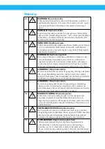
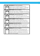
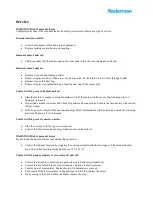
WARNING! Risk of personal injury. 

Completely disconnect the vacuum cleaner from all power sources before any type of service. 

1.2 

Control the cable and plug, and replace it is if damaged. 

1.5 

Replace leaking suction hoses and couplings. 

2.1 

Replace worn out, aged and leaking gaskets. 

2.4 

Repair or replace worn out filters to avoid wear and tear of the turbine rotor or blow through of health 
hazardous materials. 

2.5 

Replace torn or full antistatic dust bag. 
Repair or replace reusable dust bag. If it is clogged, wash or shake it clean. 

2.6 

Clean the water level limiting device regularly and examine it for signs of damage. 

3.1 

Start the motors in sequence using the main switch. If the main switch does not function properly or is 
damaged, replace it. 

3.2 

If specified vacuum is not reached, check all gaskets and connections. Execute the vacuum test with 
suction inlet(s) closed. 

3.3 

If the noise level is higher than the maximum specified, dismantle the silencer hood and check the 
silencing material. Replace it if it is damaged. 

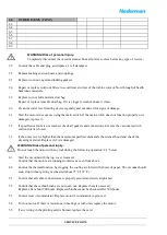
WARNING! Risk of personal injury. 

Do not touch the motor with any tool during the following operation ‘4.1’ below. 

4.1 

Start the vacuum with the top cover removed. 
Control that the motors are running clockwise as seen from above. 

4.2 

Control the thermal function by clogging the cooling air inlets with sheets of paper. The vacuum should 

soon stop without getting overheated (about 75˚C/167 ˚F). 

5.1 

Control that all cable connections are properly secured and screws tightened. 

5.2 

Control that the carbon brushs are not worn out. Replace them if necessary. 
Replace after about 900 hours. Replaced brushes must be checked after 500 hours. 

5.3 

Control wear of commutator. Replace motor if commutator is grooved. 

5.4 

Turn on motor. If there is resistance in bearings or turbo fan, replace the motor. 

5.5 

If any wiring in the printing card is burned, replace the card. 

Summary of Contents for 42172207

Page 1: ... manual CS NÁVOD K OBSLUZE DA BETJENINGSVEJLEDNING DE BEDIENUNGSANLEITUNG ES MANUAL DE INSTRUCCIONES FI KÄYTTÖOHJEET FR MANUEL D INSTRUCTION HU FELHASZNÁLÓI KÉZIKÖNYV IT MANUALE D ISTRUZIONE NL HANDLEIDING NO BRUKSANVISNING PL INSTRUKCJA UŻYTKOWANIA RO MANUAL DE UTILIZARE RU РУКОВОДСТВО ПО ЭКСПЛУАТАЦИИ SV ANVÄNDARMANUAL Instruction manual ...

Page 2: ...s 2006 42 EC 87 404 EEC Normas EN 286 1 EN ISO 12100 Español ES Overensstemmelseserklæring Vi AB Ph Nederman Co erklærer som eneansvarlige at produkterne fra Nederman A enhederne 014A 105A 106A 112A 113A 115A 116A 117A 139A 206A 216A 218A 221A 305A 306A 315A 316A 405A 415A 425A 426A 450A 460A 470A 471A 500A 510A 570A 580A 581A 600A 700A 710A 720A 721A og 722Aog tilbehøret dertil som denne erklærin...

Page 3: ...139A 206A 216A 218A 221A 305A 306A 315A 316A 405A 415A 425A 426A 450A 460A 470A 471A 500A 510A 570A 580A 581A 600A 700A 710A 720A 721A i 722A wraz z akcesoriami których dotyczy niniejsza deklaracja są zgodne z następującymi Dyrektywy 2006 42 EC 87 404 EEC Normy EN 286 1 EN ISO 12100 Polski PL AB Ph Nederman Co P O Box 602 SE 251 06 Helsingborg Sweden Erik Blix Plant Manager Заявление о соответстви...

Page 4: ...splosivt eller meget brandfarligt materiale eller på steder hvor sådant materiale forekommer skal du kontakte din nærmeste autoriserede distributør eller Nederman for at få teknisk rådgivning NO ADVARSEL Eksplosjonsfare Hvis denne enheten skal brukes til oppsamling av helsefarlige eksplosive eller lett antennelige materialer eller i områder der dette forekommer må du ta kontakt med din nærmeste au...

Page 5: ...le di questo tipo contattare il distributore autorizzato più vicino o Nederman per un parere tecnico FR AVERTISSEMENT Risque d explosion Si cet appareil doit être utilisé pour la collecte de matériaux dangereux explosifs ou très inflammables ou dans les zones où ce type de matériaux est présent contactez votre distributeur ou Nederman pour des conseils techniques CS VÝSTRAHA Nebezpečí výbuchu Bude...

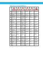
Page 6: ...bar Váltóáram Mozgó pneumatikus munkahenger Ingatag Zaj Becsípődés veszélye PL Powietrze sprężone maks 8 bar Prąd zmienny Przesuwający się siłownik pneumatyczny Niestabilność Hałas Niebezpie czeństwo wciągnięcia ES Aire comprimido máx 8 bar Corriente alterna Cilindro neumático en movimiento Inestable Ruido Riesgo de pel lizcamiento RO Aer comprimat maximum 8 bari Curent alternativ Cilindru pneumat...

Page 7: ...connect the vacuum cleaner from all power sources before any type of service or transportation Disconnect the vacuum cleaner with a 1 phase motor before removing its motor assembly Only authorised personnel are allowed to carry out electrical installation Replace all damaged components from a vacuum overpressure with original spare parts Do not remove the cover of the vacuum clean once it is start...

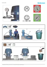
Page 8: ...ning handle See the filter cleaning section Vacuum cleaner use wet material 1 Connect power supply 2 Turn on switch to start the vacuum cleaner 3 When the container is full the suction flow is shut off by the float ball 4 Switch off the vacuum cleaner before emptying the container Vacuum cleaner use NCF filter 1 Connect power supply 2 Turn on switch to start the vacuum cleaner 3 When the filter is...

Page 9: ...ck all gaskets and connections Execute the vacuum test with suction inlet s closed If the noise level is higher than the maximum specified dismantle the silencer hood and check the silencing material Replace it if it is damaged Control with top cover removed unit on Start the vacuum with the top cover removed Control that the motors are running clockwise as seen from above WARNING Risk of personal...

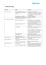
Page 10: ...logged open it with a rod Clogged filter For filter bag and cartridge filter cleaning please see operation instruction NCF filter cleaning check filter cleaning function by listening to noise from blow out valve If not in operation check quick coupling and function of blow out valve Leaking suction hose Tape or replace suction hose Leaking gaskets Damaged neoprene gasket remove and replace Use sui...

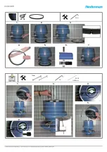
Page 11: ...ion hose s 1 6 Preseparator cyclone 1 7 Accessories 1 8 Other items specify 2 0 CONTROL WITHOUT RUNNING INSIDE 2 1 Gasket s 2 2 Lid vacuum head 2 3 Container s 2 4 Filter s 2 5 Dustbag 2 6 Float ball 2 7 Other items specify 3 0 CONTROL RUNNING TOP COVER INSTALLED 3 1 Start stop switch function 3 2 Vacuum 3 3 Noise level 4 0 CONTROL RUNNING TOP COVER DISMANTLED 4 1 Rotation motors 4 2 Thermoswitch ...

Page 12: ... and connections Execute the vacuum test with suction inlet s closed 3 3 If the noise level is higher than the maximum specified dismantle the silencer hood and check the silencing material Replace it if it is damaged WARNING Risk of personal injury Do not touch the motor with any tool during the following operation 4 1 below 4 1 Start the vacuum with the top cover removed Control that the motors ...

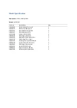
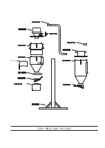
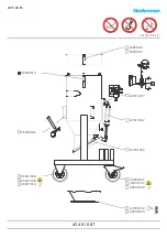
Page 13: ...let 1 43461007 Silo S200 f wall d76 1 43751008 Frame S200 H 4200 1 43630100 Discharge valve pneu 1 43640003 Bagholder f disc valve pneu 1 43650104 Plastic bag S50 25pcs 1 43561005 Coarse grain sep S200 d95 76 1 43834500 Suction hose PU d76 L 2m 1 43630001 Discharge valve manual 1 43903091 Bend d76 f d76 inlet 1 43884462 Pipe connection d95 76 1 43627003 Abrasion plate f silo S200 1 ...

Page 14: ...722A NE76 S200 42172207 43627003 ...

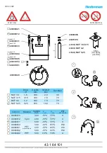
Page 15: ... 2 7 2500 25 564 73 5 43905005 NE 64 4 3 6800 68 330 77 0 43905006 NE 66 4 1 3800 38 630 76 5 43905007 NE 74 5 3 7800 78 318 75 0 43905008 NE 76 5 4 4800 48 690 78 0 43905009 NE 96 8 6 6800 68 660 78 0 43905011 NE 56x2 5 4 2500 25 1128 76 5 43905005 NE 96x2 17 2 6800 68 1320 79 0 43905011 Noise level distance 3 m height 1 1 m Air press ure 7 bar E jector body Max air flow Noise level Vacuum produc...

Page 16: ...MAX 8 bar 43214001 43214100 S 235JR S t37 2 Ex Z Y 28 01 2013 43 0 400 26 ...

Page 17: ...F 1 6 1 6 300 2 9 36 NCF 3 15 3 15 300 7 6 70 NCF 4 2 4 2 400 7 6 70 NCF 5 25 5 25 500 10 4 70 Code no Material Candle mm Tmin Tmax EN 60335 2 69 43906010 Vyon 300 10ºC 70ºC U 43906012 400 10ºC 70ºC U 43906011 500 10ºC 70ºC U 43906050 PET w membrane 300 10ºC 80ºC H12 43906051 400 10ºC 80ºC H12 43906052 500 10ºC 80ºC H12 43906042 PPF 500 10ºC 110ºC U System 200 System 200 System 50 System 50 439010...

Page 18: ...43901052 43901050 43999021 43999721 43908006 43999012 S235JR St37 2 43907007 43907107 43907009 43907008 43907108 43907010 43915067 43915027 43901054 ì ìí ì ìí ððï ...

Page 19: ...43901052 43901050 43999021 43999721 43908006 43999012 S 235JR S t37 2 43907007 43907107 43907009 43907008 43907108 43907010 43915067 43915027 43901054 2013 02 05 43 4 61 007 ...

Page 20: ...08 05 2009 MAX 1 5 bar 43901007 43999071 43999200 43999069 43999073 43915070 43999075 43999072 ì ì ì ì ì ìí ê íð ððï ...

Page 21: ...28 01 2013 MAX 1 5 bar 43901007 43999071 43999200 43999069 43999073 43915070 43999075 43999072 43 6 30 100 ...

Page 22: ...28 01 2013 43901070 Alt1 System 50 System 200 43901051 43901052 43901053 43901050 S235JR St37 2 43561005 ...

Page 23: ...11 02 2010 Material C F PE 40 C 60 C 40 F 140 F PVC 20 C 70 C 4 F 158 F PUR 40 C 90 C 40 F 194 F 43 8 34 500 ...

Page 24: ...18 06 2008 Addendum to Manual ...

Page 25: ... NE mmWC kPa Nm hr 22 2100 21 306 32 3100 31 342 42 4200 42 360 52 5200 52 342 56 2500 25 564 64 6800 68 330 66 3800 38 630 74 7800 78 318 76 4800 48 690 96 6800 68 660 56x2 2500 25 1128 96x2 6800 68 1320 ...

Page 26: ...6 8 bar OK 1 2 3 1 2 3 ...

Page 27: ...1 4 2 5 3 6 7 3mm 1 2 3 4 5 10mm 1 4 Ø 2 5 L 500mm ...

Page 28: ...1 7 12 4 10 14 2 8 13 5 11 15 3 9 6 16 A F B B C 10mm A E F B C D D G G Nederman Norclean AS P O Box 2033 N 3202 Sandefjord NORWAY Tel 47 33 42 05 50 Fax 47 33 42 50 51 info norclean no ...

Page 29: ......

Page 30: ......

Page 31: ......

Page 32: ...www nederman com ...

Reviews: