background image

Hose Reel 884

ES

1

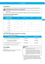
Instale el Hose Reel 884 en el lugar previsto.

2

Pasar la manguera por la salida del arrollador y su-
jetar su extremo a la rótula. Extender la mangue-
ra desenrollada sobre el suelo en toda su longitud.
Consulte la longitud máxima de la manguera en la
etiqueta de identificación del carrete.

3

Suelte el trinquete de seguridad. Asegúrese de
que la manguera esté totalmente controlada sin
ningún tipo de holgura. No suelte la manguera an-
tes de que el tope de la misma toque la salida de la
manguera.

4

Libere el mecanismo de retención tirando ligera-
mente de la manguera en el sentido de la flecha. A
continuación, deje que la manguera se enrolle des-
pacio en el tambor del enrollador.

5

Monte el tope de la manguera a la longitud desea-
da. véase la 

Sección 6.1 Ajuste de la tensión del

muelle

 articulo 1.

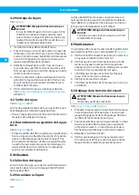
4.2 Salida de manguera

Consulte 

Ilustración 2

 pos. A.

La salida de manguera se puede girar y colocar en va-
rias posiciones.
• Seleccione un ángulo, para asegurar un ángulo de

giro minimo de la manguera a la salida.

4.3 Conexión al sistema de tuberías

Consulte 

Ilustración 2

 pos. B.

• El Hose Reel 884 debe ser conectado a la pipa con

una manguera flexible de 0,5 metros como minimo.
Esta manguera de entrada se debe de hacer pasar a
través del anillo (*) que vá montado a brazos de fija-
ción. Comprobar que la manguera flexible de entra-
da no está retorcida o demasiado tensa. Deberia fi-
jarse una valvula de cierre en la tuberia de alimenta-
ción antes de la conexión al carrete enrollador.

5 Uso

5.1 Selección de la manguera

Para seleccionar la manguera, consulte las dimensio-
nes y la presión de funcionamiento en la etiqueta de
identificación del Hose Reel 884.

5.2 Mecanismo de trinquete

Consulte 

Ilustración 3

.

El Hose Reel 884 se entrega con un mecanismo de
trinquete que retiene la manguera en la posición des-
enrollada requerida. El trinquete se desacoplará tiran-
do un poco más de la manguera, con lo cual ésta se en-
rollará en el tambor.

¡ADVERTENCIA! Riesgo de lesión personal
No suelte la manguera hasta que el tope de la
manguera se encuentre con la salida de la man-
guera.

6 Mantenimiento

Recomendado hacer regularmente mantenimiento, al
menos una vez al año. Ver también 

Ilustración 6

.

A

Compruebe el funcionamiento del muelle proban-
do si la manguera se enrolla correctamente.

B

Controlar que no haya fugas en la rotula giratoria y
en las conexiones de la manguera. Cambiar la junta
si es necesario. Limpiar la rotula giratoria y de las
conexiones.

C

Controlar que la manguera esté en buen estado.
Limpiar la manguera si tiene aceite o suciedad.

D

Controlar el mecanismo de retención del enrolla-
dor (trinquete).

E

Controlar el montaje del enrollador en la pared o el
techo.

6.1 Ajuste de la tensión del muelle

¡ADVERTENCIA! Riesgo de lesión personal
Utilice guantes protectores.

Consulte 

Ilustración 5

Ilustración 6

 y 

Ilustración 7

.

1

Enrollar la manguera hasta que el tope se de-ten-
ga contra la boca de salida. Sacar la manguera has-
ta la posición de retención. Desatornillar el tope y
la herramienta conectada a la manguera.

2

Girar el tambor con toda la manguera enrollada:
una vuelta en dirección de la flecha negro para au-
mentar la tensión del muelle, una vuelta de direc-
ción de la flecha gris para reducir la tensión del
muelle.

3

Monte el tope de manguera y la herramienta.

4

Compruebe que se pueda extraer la longitud re-
querida de la manguera sin tirar del muelle hasta
su límite. No use una tensión de resorte mayor de
la necesaria.

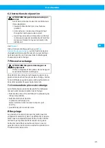
6.2 Instrucciones para la reparación

¡ADVERTENCIA! Riesgo de lesión personal
Antes de efectuar cualquier operación en el
Hose Reel 884:
• Desconecte el suministro de aire/agua/acei-

te/grasa.

• Ponga el seguro antes de cambiar la mangue-

ra o el cabezal.

• Antes de ponerlo en el carrete libere la ten-

sión del muelle para mover el topo de man-
guera hasta conseguir que la manguera se re-
coja completmente.

Consulte 

Ilustración 7

.

Instrucciones para montar la manguera, ver 

Sec-

ción 4.1 Montaje de la manguera

. Las instrucciones pa-

ra cambiar el casete del muelle, el codo giratorio o la
junta se adjuntan a cada pieza de repuesto.

34

Summary of Contents for 884

Page 1: ...r manual CS N VOD K OBSLUZE DA BRUGERVEJLEDNING DE BEDIENUNGSANLEITUNG ES MANUAL DE USUARIO FI K YTT OHJE FR MANUEL DE L UTILISATEUR IT MANUALE DELL UTENTE NO BRUKERMANUAL NL GEBRUIKERSHANDLEIDING PL...

Page 2: ...Hose Reel 884 Trace back information Workspace Main version a68 Checked in 2022 10 28 Skribenta version 5 5 022...

Page 3: ...Hose Reel 884 Declaration of Conformity 4 Figures 8 English 11 esk 16 Dansk 21 Deutch 26 Espa ol 31 Suomi 36 Fran ais 41 Italiano 46 Norsk 51 Nederlands 56 Polski 61 Svenska 66 71 3...

Page 4: ...vel overensstemmelseserkl ringen som den tek niske dokumentation DE Deutch Konformit tserkl rung Wir AB Ph Nederman Co erkl ren in alleiniger Verantwortung dass das Nederman Produkt Hose Reel 884 Art...

Page 5: ...samsvarserkl ringen og den tekniske filen NL Nederlands Conformiteitsverklaring Wij AB Ph Nederman Co verklaren onder onze verantwoordelijkheid dat het Nederman product Hose Reel 884 artikelnr en verm...

Page 6: ...Hose Reel 884 3086 84 AB Ph Nederman Co P O Box 602 SE 251 06 Helsingborg Sweden Anna Cederlund Product Center Manager Technical Product Management 2022 10 28 6...

Page 7: ...pply of Machinery Safety Regulations 2008 Standards EN ISO 12100 2010 EN ISO 20607 2019 The name and signature at the end of this document is the person responsible for the declaration of conformity T...

Page 8: ...Hose Reel 884 Figures max 4 m 1 NB max 5 mm A B 2 2 8...

Page 9: ...Hose Reel 884 1 m 1 m 1 m A B 3 1 2 3 4 2 1 4 9...

Page 10: ...Hose Reel 884 5 B A C E 6 3 2 7 10...

Page 11: ...scription 13 3 1 Technical data 13 3 2 Sound pressure and sound power 13 4 Installation 13 4 1 Hose fitting 13 4 2 Hose outlet 14 4 3 Connection to the pipework system 14 5 Use 14 5 1 Selecting hose 1...

Page 12: ...iginal spare parts and accessories Contact the nearest au thorized distributor or Nederman for advice on tech nical service and obtaining spare parts If there are any damaged or missing parts when the...

Page 13: ...The Hose Reel 884 can be wall floor or ceiling mounted according to the pictures NOTE Maximum installation height above floor level is 4 m When choosing the mounting place it should be notified that t...

Page 14: ...s do not leak Change the seal if required Clean the swivel and couplings C Check that the hose is intact Clean the hose if oily or dirty D Check the ratchet mechanism E Check the mounting of the reel...

Page 15: ...c h Quantity of the parts required 8 Recycling The product has been designed for component mater ials to be recycled Different material types must be handled according to relevant local regulations C...

Page 16: ...opis 18 3 1 Technick daje 18 3 2 Akustick tlak a akustick v kon 18 4 Instalace 18 4 1 Mont hadice 18 4 2 V stup hadice 19 4 3 P ipojen potrubn ho syst mu 19 5 Pou it 19 5 1 V b r hadice 19 5 2 Mechani...

Page 17: ...t a p slu enstv od spole nosti Nederman Pot ebujete li jakoukoliv tech nickou radu ohledn dr by nebo z sk n n hradn ch sou sti kontaktujte sv ho nejbli ho autorizovan ho prodejce spole nosti Nederman...

Page 18: ...alace Viz Obr zek 1 Hose Reel 884 m e b t namontov n na st n podla ze nebo na strop podle obr zku POZN MKA Maxim ln v ka instalace nad podlahou je 4 m P i v b ru mont n ho povrchu je nutn vz t v vahu...

Page 19: ...da oto n spojka a spojky hadice dn t sn V p pad pot eby vym te t sn n Vy ist te oto nou spojku a hadicov spojky C Zkontrolujte zda je hadice neporu en Pokud je hadice zne i t n nebo zama t n vy ist te...

Page 20: ...a r t s e a r c h Mno stv po adovan ch d l 8 Recyklace V robek byl vyroben tak aby se materi ly v n m obsa en daly recyklovat S r zn mi typy materi l je t e ba nakl dat dle platn ch m stn ch p edpis V...

Page 21: ...skrivelse 23 3 1 Tekniske data 23 3 2 Lydtryk og lydeffekt 23 4 Installation 23 4 1 Montering af slangen 23 4 2 Slangeudl b 24 4 3 Tilslutning til r rsystemet 24 5 Anvendelse 24 5 1 Valg af slange 24...

Page 22: ...s originale reserve dele og originalt tilbeh r fra Nederman Kontakt n r meste autoriserede forhandler eller Nederman for at f r d om teknisk service og anskaffelse af reservede le Hvis produktet lever...

Page 23: ...m vist p billederne BEM RK Den maksimale installationsh jde over gulv niveau er 4 m N r du v lger monteringssted skal du v re opm rksom p at slangens levetid kan p virkes af kemikalier og st rk UV ell...

Page 24: ...Reng r drejeled og koblinger C Kontroller at slangen er intakt Reng r slangen hvis den er olieret eller snavset D Kontroll r skraldemekanismen E Kontroll r monteringen af rullen p v ggen eller i loft...

Page 25: ...e a r c h Antallet af reservedele 8 Genbrug Produktet er designet til komponentmaterialer der kan genanvendes Forskellige materialetyper skal h ndteres i henhold til relevante lokale regler Kon takt d...

Page 26: ...3 Beschreibung 28 3 1 Technische Daten 28 3 2 Schalldruck und Schallleistung 28 4 Installation 28 4 1 Schlauchmontage 28 4 2 Schlauchausgang 29 4 3 Anschluss an das Leitungssystem 29 5 Bedienung 29 5...

Page 27: ...rt werden Wenden Sie sich f r Hilfestellung zu technischem Service und f r Ersatzteile bitte an Ih ren Fachh ndler oder direkt an Nederman Wenn Sie bei Anlieferung des Produktes feststellen dass Teile...

Page 28: ...erteter Schallleistungspegel 104 5 dB A 92 6 dB A Ref 2006 42 EC 1 7 4 2 u ISO 3744 4 Installation Siehe Abbildung 1 Der Hose Reel 884 kann f r Wand Boden oder De ckenmontage verwendet werden BEACHTEN...

Page 29: ...errklinkenme chanismus geliefert der den Schlauch in der erforder lichen herausgezogenen Stellung h lt Die Sperrklinke l st sich wenn der Schlauch etwas weiter herausge zogen wird Der Schlauch wird da...

Page 30: ...a n c o m 7 1 Bestellung von Ersatzteilen Bei der Bestellung von Ersatzteilen ist immer Folgen des anzugeben Teile und Kontrollnummer siehe Typenschild am Produkt Ersatzteilnummer mit Beschreibung sie...

Page 31: ...t cnicos 33 3 2 Presi n ac stica y potencia ac stica 33 4 Instalaci n 33 4 1 Montaje de la manguera 33 4 2 Salida de manguera 34 4 3 Conexi n al sistema de tuber as 34 5 Uso 34 5 1 Selecci n de la ma...

Page 32: ...orios originales Nederman P ngase en contacto con el distribuidor autorizado m s pr ximo o con Ne derman para asesoramiento sobre servicio t cnico y obtenci n de piezas de repuesto Si hay alg n compo...

Page 33: ...stica ponderada A 104 5 dB A 92 6 dB A Ref 2006 42 CE 1 7 4 2 u ISO 3744 4 Instalaci n Consulte Ilustraci n 1 El Hose Reel 884 se puede montar en el techo en el suelo o en la pared como muestran las...

Page 34: ...en el tambor ADVERTENCIA Riesgo de lesi n personal No suelte la manguera hasta que el tope de la manguera se encuentre con la salida de la man guera 6 Mantenimiento Recomendado hacer regularmente mant...

Page 35: ...haga pedidos de piezas de repuesto indique siempre lo siguiente N mero de la pieza y de control v ase la placa de identificaci n del producto Indique el n mero y el nombre de la pieza de repuesto visi...

Page 36: ...allisuusohjeet 37 3 Kuvaus 38 3 1 Tekniset tiedot 38 3 2 nenpaine ja niteho 38 4 Asennus 38 4 1 Letkun asennus 38 4 2 Letkunohjain 39 4 3 Liitt minen putkistoon 39 5 K ytt 39 5 1 Letkun valinta 39 5 2...

Page 37: ...k yt t en ainoastaan Nederman alkuper isi varaosia ja tarvikkeita Jos haluat neuvoja teknisist palveluis ta tai tilata varaosia ota yhteys l himp n valtuu tettuun j lleenmyyj n tai Nederman Jos tuott...

Page 38: ...ti HUOMAUTUS Maksimi asennus korkeus lattiasta on 4 m Ota huomioon asennuspaikkaa valitessasi ett kemikaalit ja voimakas UV tai l mp s teily voivat lyhent letkun kestoik Valitse Hose Reel 884 tasainen...

Page 39: ...u on ehj Pyyhi ljyinen ja likai nen letku puhtaaksi D Tarkista r ikk mekanismi E Tarkista kelan kiinnitys sein ss tai katossa 6 1 Jousen j nnityksen s t VAROITUS Henkil vahingon riski K yt suojak sine...

Page 40: ...e on suunniteltu siten ett osien materiaalit voi daan kierr tt Eri materiaalityypit on k sitelt v pai kallisten s d sten mukaan Ota kysymyksiss yhteys j lleenmyyj n tai N e d e r m a n kun tuote heite...

Page 41: ...iques techniques 43 3 2 Pression acoustique et puissance acoustique 43 4 Installation 43 4 1 Montage du tuyau 44 4 2 Sortie de tuyau 44 4 3 Raccordement au syst me de tuyauterie 44 5 Utilisation 44 5...

Page 42: ...derman d origine Pour obtenir des conseils techniques et des pi ces de re change contacter le distributeur agr le plus proche ou Nederman En cas de pi ces endommag es ou manquantes la livraison du pro...

Page 43: ...Tirer B Rembobiner LpA niveau de pression acoustique pond r A 90 8 dB A 77 5 dB A LpC niveau de pression acous tique instantan pond r C 114 8 dB A 104 9 dB A LwA niveau de puissance acoustique pond r...

Page 44: ...tuyauterie avant le raccordement du flexible 5 Utilisation 5 1 S lection du tuyau Lors du choix du tuyau se reporter aux dimensions et la pression de service sur la plaque d identification du Hose Ree...

Page 45: ...nge et accessoires N e d e r m a n d origine Pour obtenir des conseils techniques ou des rensei gnements concernant les pi ces de rechange contac ter le distributeur agr le plus proche ou N e d e r m...

Page 46: ...8 3 1 Dati tecnici 48 3 2 Pressione sonora e potenza sonora 48 4 Installazione 48 4 1 Montaggio del tubo 48 4 2 Braccio uscita tubo 49 4 3 Collegamento al sistema di tubazioni 49 5 Utilizzo 49 5 1 Sel...

Page 47: ...rman per consigli relativi all assistenza tecnica e per richiedere i ricambi In ca so di componenti danneggiati o mancanti al momento della consegna del prodotto avvisare immediatamen te il corriere o...

Page 48: ...A 104 9 dB A LwA potenza sonora ponderata A 104 5 dB A 92 6 dB A Rif 2006 42 EC 1 7 4 2 u ISO 3744 4 Installazione Vedere Figura 1 L Hose Reel 884 si pu montare a parete pavimen to soffitto NOTA L al...

Page 49: ...NZA Rischio di lesioni personali Non rilasciare il flessibile finch il suo fermo non raggiunge l uscita 6 Manutenzione Si consiglia di eseguire la manutenzione regolarmente o almeno una volta all anno...

Page 50: ...Numero di serie e numero di controllo fare riferi mento alla targhetta identificativa del prodotto Il numero di riferimento del parti colare di ricambio e il nome vedi w w w n e d e r m a n c o m e n...

Page 51: ...joner 52 3 Beskrivelse 53 3 1 Tekniske data 53 3 2 Lydtrykk og lydeffekt 53 4 Installasjon 53 4 1 Montere slange 53 4 2 Slangeutgang 54 4 3 Koble til r rsystem 54 5 Bruk 54 5 1 Velge slange 54 5 2 Spe...

Page 52: ...onell som bare bruker originale reservedeler Ta kontakt med din n rmeste autoriserte forhandler eller Nederman for f r d og tips om teknisk service og for bestilling av reservede ler Ved skade eller m...

Page 53: ...ller i tak som vist p bildene MERK Maksimal installasjonsh yde over gulvet er 4 m N r du velger monteringssted b r du v re klar over at slangens levetid kan p virkes av kjemikalier og sterke UV str le...

Page 54: ...anismen E Kontroller monteringen av trommelen i vegg eller tak 6 1 Justering av fj rspenn ADVARSEL Fare for personskade Bruk vernehansker Se Figur 5 Figur 6 og Figur 7 1 La slangen rulles inn til den...

Page 55: ...struert slik at komponentmateriale ne kan resirkuleres De ulike materialtypene m h nd teres iht gjeldende lokale forskrifter Ta kontakt med distribut ren eller N e d e r m a n hvis du er i tvil n r du...

Page 56: ...ving 58 3 1 Technische gegevens 58 3 2 Geluidsdruk en geluidsvermogen 58 4 Installatie 58 4 1 Slangaansluiting 58 4 2 Slanguitloop 59 4 3 Aansluiting op het leidingsnet 59 5 Gebruik 59 5 1 Keuze van d...

Page 57: ...Nederman Neem contact op met uw dichtstbijzijnde erkende Nederman dealer voor tech nisch advies en reserveonderdelen Indien het product bij de levering is beschadigd of er ontbreken onderde len dienen...

Page 58: ...allatie Zie Afbeelding 1 De Hose Reel 884 kan aan de muur vloer of plafond worden gemonteerd zie de afbeeldingen OPMERKINGEN Maximale montagehoogte vanaf de vloer 4 m Houd er bij het kiezen van de mon...

Page 59: ...g is 6 Onderhoud Volgend onderhoud wordt regelmatig of minimaal eens per jaar aanbevolen Zie ook Afbeelding 6 A Controleer de werking van de veer door te testen of de slang goed oprolt B Controleer of...

Page 60: ...steeds het volgende te vermelden Onderdeel en controlenummer raadpleeg het pro ductidentificatieplaatje Detailnummer en naam van het reserveonderdeel zie w w w n e d e r m a n c o m e n s e r v i c e...

Page 61: ...s 63 3 1 Dane techniczne 63 3 2 Ci nienie akustyczne i moc akustyczna 63 4 Instalacja 63 4 1 Monta w a 64 4 2 Wylot w a 64 4 3 Pod czenie do instalacji rurowej 64 5 U ytkowanie 64 5 1 Dob r w a 64 5 2...

Page 62: ...konserwacj i naprawami przez wykwalifikowanych pracownik w oraz z wykorzysta niem wy cznie oryginalnych cz ci zamiennych W ra zie konieczno ci skorzystania z pomocy serwisu tech nicznego i zam wienia...

Page 63: ...e warto ci Warto d wi ku A Wyci gn B Nawin LpA ci nienie akustyczne w skali A 90 8 dB A 77 5 dB A LpC Chwilowe ci nienie aku styczne wa one w skali C 114 8 dB A 104 9 dB A LwA Moc d wi ku w skali A 10...

Page 64: ...echanizm zapadkowy Patrz Ilustracja 3 Zwijacz Hose Reel 884 jest dostarczany z mechani zmem zapadkowym kt ry utrzymuje w w wymaga nej pozycji po wyci gni ciu Zapadk zwalnia si przez lekkie wyci gni ci...

Page 65: ...z ci zamiennych W przypadku zamawiania cz ci zawsze nale y poda wa nast puj ce informacje Numer cz ci i numer kontrolny patrz tabliczka znamionowa produktu Numer szczeg owy i nazw cz ci zamiennej patr...

Page 66: ...oner 67 3 Beskrivning 68 3 1 Tekniska data 68 3 2 Ljudtryck och ljudeffekt 68 4 Installation 68 4 1 Slangkoppling 68 4 2 Slangutlopp 69 4 3 Anslutning till r rsystemet 69 5 Anv ndning 69 5 1 V lja sla...

Page 67: ...naldelar och tillbeh r fr n Neder man Kontakta n rmaste auktoriserade terf rs ljare eller Nederman f r r dgivning vid teknisk service samt f r att erh lla reservdelar Kontakta omedelbart spe dit ren o...

Page 68: ...SO 3744 4 Installation Se Figur 1 Hose Reel 884 kan monteras p v gg golv eller i tak enligt bildexemplen NOTERA Maximal montageh jd fr n golv r 4 m Observera vid val av montageplats att slangens livsl...

Page 69: ...r C Kontrollera att slangen r hel Reng r t r oljig och nedsmutsad snavsed slang D Kontrollera sp rrmekanismen E Kontrollera upprullarens inf stning p v gg eller i tak 6 1 Inst llning av fj derkraft VA...

Page 70: ...r designad s att komponentmaterialet kan tervinnas De olika materialtyperna m ste han teras i enlighet med till mpliga lokala best mmelser Kontakta leverant ren eller N e d e r m a n om det skulle upp...

Page 71: ...Hose Reel 884 8 1 72 2 72 2 1 72 2 2 72 3 73 3 1 73 3 2 73 4 73 4 1 73 4 2 74 4 3 74 5 74 5 1 74 5 2 74 6 74 6 1 74 6 2 74 7 74 7 1 74 8 74 ZH 71...

Page 72: ...Hose Reel 884 ZH 1 Nederman Nederman Nederman Nederman EC Nederman Nederman Nederman 2 2 1 2 2 72...

Page 73: ...5 MPa 5 0 MPa 18 0 MPa 35 0 MPa 3 2 3 A B LpA A 90 8 dB A 77 5 dB A LpC C 114 8 dB A 104 9 dB A LpA A 104 5 dB A 92 6 dB A 2006 42 EC 1 7 4 2 u ISO 3744 4 1 Hose Reel 884 4 m Hose Reel 884 7600 N 4 1...

Page 74: ...Hose Reel 884 5 2 3 Hose Reel 884 6 6 A B C D E 6 1 5 6 7 1 2 3 4 6 2 Hose Reel 884 1 7 4 1 7 N e d e r m a n N e d e r m a n w w w n e d e r m a n c o m 7 1 w w w n e d e r m a n c o m e n s e r v i...

Page 75: ...www nederman com...

Reviews: