Trolley Return Unit 920/1500
EN
20
Cable W9 to W16
Cable W9 to W16 is not included in the suction trolley return. EKK or EKLK is a suitable
cable that is recommended. See Appendix A, Cable connections overview (coloured
boxes).
Cables W9, W10 and W16 are control cables, low voltage
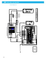
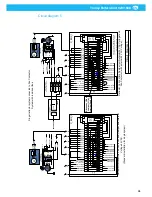
installation 5 VDC. Connect cables W9, W10 and W16 according
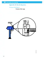
to Appendix B, ‘Circuit diagram 2’ , ‘Circuit diagram 3’ or
‘Circuit diagram 4’ depending on the chosen configuration.
Cable W11 is a low-voltage installation 24 VAC. The cable routing of W11 can be
complex depending on the location of the damper. If you use a cable with a maximum
outer diameter of 7.4 mm, it is possible to route it in the aluminium profile’s vacant slot
(equivalent slot as W2 is routed in). One suggestion is to use Ölflex/Ryflex 7G 0.75
mm2 that fits precisely inside the extraction channel slot. Connect cable according to
Appendix B ‘Circuit diagram 5’.
Cable W12 is a control cable, which is connected to Fan Starter
or Fan Inverter. Connect cable according to Appendix B,
‘Circuit diagram 5’, ‘Circuit diagram 6’ ‘Circuit diagram 7’ or ‘Circuit diagram 8’
depending on the choosen configuration.
Before connecting cable W13, W14 and W15, go to
Section ‘5.4 Electrical continuous test (2 persons required)’ and perform an
electrical continuous test.
Cables W13 to W15 with the associated power components constitute a power current
installation. Power components are fan, working switches and starting devices for the fan.
A qualified electrician must perform the installation and the connection to the network.
Green-marked components and pink marked cables are included in the suction trolley
return and are installed by Nederman’s electricians.
Blue-marked components, and yellow-marked cables are not included in the suction
trolley return and are installed by a local qualified electrician.
Orange-marked cables are installed by the installation team. These cables are not included
in the suction trolley return.
Table 5-2: Cable table
Cable
Circuit diagram
Type
W9, W10, W16
2, 3, 4.
5 V DC Control cable to Control Box. 5 V DC Control
cable to Control Box.
W11
5, 6, 7, 8
24 V DC Control cable to Damper.
W12
5, 6, 7, 8
24 V DC Control cable to Fan Starter or Fan Inverter.
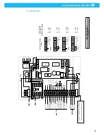
W13
1, 10
Mains power cable to Drive unit and Safety switch.
W14, W15
See Fan Starter or Fan Inverter
documentation. See also Section
9.2 Cable connections overview.
Mains power cable to Safety switch and Fan Starter
or Fan Inverter.
5.4
Electrical continuous test (2 persons required)
Before you power up the system it is recommended to do an electrical wiring test to
control if the wiring is done according to the electrical drawings.
You need a Voltage multimeter with buzz test.
Make sure that the Trolley Return System’s power supply is off.
Summary of Contents for 920/1500
Page 2: ...Trolley Return Unit 920 1500 2 ...
Page 3: ...Trolley Return Unit 920 1500 3 English 4 ...
Page 28: ...Trolley Return Unit 920 1500 EN 28 Appendix A Cable connections Cable connections overview ...
Page 29: ...Trolley Return Unit 920 1500 29 EN Simple cable connections overview ...
Page 30: ...Trolley Return Unit 920 1500 EN 30 Appendix B Circuit diagrams Driving slot circuit diagram ...
Page 31: ...Trolley Return Unit 920 1500 31 EN Circuit diagram 1 ...
Page 32: ...Trolley Return Unit 920 1500 EN 32 Circuit diagram 2 ...
Page 33: ...Trolley Return Unit 920 1500 33 EN Circuit diagram 3 ...
Page 34: ...Trolley Return Unit 920 1500 EN 34 Circuit diagram 4 ...
Page 35: ...Trolley Return Unit 920 1500 35 EN Circuit diagram 5 ...
Page 36: ...Trolley Return Unit 920 1500 EN 36 Circuit diagram 6 ...
Page 37: ...Trolley Return Unit 920 1500 37 EN Circuit diagram 7 ...
Page 38: ...Trolley Return Unit 920 1500 EN 38 Circuit diagram 8 ...
Page 39: ...Trolley Return Unit 920 1500 39 EN Circuit diagram 9 ...
Page 40: ...Trolley Return Unit 920 1500 EN 40 Circuit diagram 10 ...
Page 41: ......
Page 42: ......
Page 43: ......
Page 44: ...www nederman com ...


