Fan Inverter
12 Using Fan Inverter
Note
The motor data and certain parameters must be set before use, see
Section 10.2.1 Quick setup and pro-
12.1 Initial start-up
Do a test run when starting the unit for the first time. This first start can be made in Local mode using the
keypad. See
Section 10.7 Local and remote control places
or ‘Changing control places’ in the ‘VACON 100 HVAC
Application Manual’.
See
. Start and stop the unit with the Start and Stop buttons to check the fan rotation. To change the
direction of the fan’s rotation, change the wiring to the motor.
WARNING! Risk of electric shock
Dangerous voltages are present when mains supply is connected. Wait at least 5 minutes after discon-
necting the supply before removing the cover of Fan Inverter or the fan motor.
WARNING! Risk of personal injury
The fan starts up automatically after an input voltage interruption if the Fan Timer or external run com-
mand is active. Do not perform any service without first disconnecting power to the system.
12.2 Setpoint parameters
Start the system with the START button. If there is any damper between the fan and the pressure tap, it has to
be open. The fan will now accelerate up to a speed creating 900 Pa system pressure in the duct at the pressure
tap.
Code
Parameter
Unit
Default
value
Selected
value
ID
Note
P3.12
PID Controller 1
NA
P3.12.2
Setpoints
NA
P3.12.2.1 Keypad SP 1
Pa
900
167
P3.12.2.2 Keypad SP 2
Pa
500
168
See
and
Section 8.2 Access the control page
.
1
Press the FUNCT button to access the ‘Control page’.
2
Adjust the setpoint by selecting the Setpoint, press OK, and then use the UP or DOWN arrow buttons on the
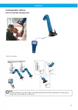
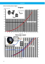
Keypad to achieve the correct extract rate from the hoods and so on, see
Section 22.3.1 C1: Airflow meas-
.
3
Press OK to accept the new setting.
A suitable value to begin with is 900 Pa. The setpoint can also be set in the parameter P 3.12.2.1 using the ‘Con-
trol page’. Please note the required pressure in the table when the system is balanced and all extraction points
have sufficient airflow, .
If there is a need for a second alternative setpoint, it can be selected by activating digital input 3 (DI3). The set-
point value can be set in parameter P 3.12.2.2, or adjusted in the ‘Control page’ while DI3 is activated, see also
.
29


