FlexFilter
WARNING! Risk of personal injury
Waste material collected in FlexFilter can con-
stitute a health risk. Always check the safety
requirements related to the specific waste
when handled.
FlexFilter dust collectors are CE marked. The CE mark-
ing is valid only if the safety instructions in this manu-
al are followed and only when original modules and
control units are installed.
3 Description
FlexFilter is primarily used for the local extraction of
dust when, for example, grinding, cutting and for va-
pours/gases when welding. FlexFilter is often a filt-
tration component in a complete vacuum installation
which may include: vacuum units, starters, control
units, and dust collectors at work sites.
FlexFilter is a modular dust collector with 2-stage fil-
tration, has a central inlet with velocity reducer and
a fully automatic filter cleaning capability. It can eas-
ily be equipped with a great variety of filter materials,
bins, emptying systems, etc.
FlexFilter can be a part of a local exhaust ventila-
tion system for separating welding fumes containing
CMR (carcinogenic mutagenic reprotoxic) substances,
where the complete system must be in compliance
with required legislations, see
www.who.int
for clas-
sification of welding fumes.
3.1 Standard models
NOTE!
The standard models are not intended for use
with combustible dust. For these environ-
ments, the EX models are the best choice.
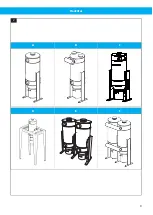
shows the FlexFilter standard models:
A
FlexFilter Single
B
FlexFilter Single RF
C
FlexFilter Single Cyclone
D
FlexFilter Single with stand
E
FlexFilter Twin
F
FlexFilter Twin RF
For additional information about stand, Cyclone and
RF modules, see
Chapter 9 Instructions for special
.
3.1.1 Measurements
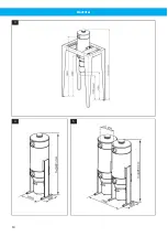
See
. All FlexFilter Single mod-
els have the same measures and all FlexFilter Twin
models have the same measures. For stand measure-
ments, see
Chapter 9 Instructions for special modules
3.2 Main components
FlexFilter is designed with modules on seven levels as
shown in
.
The modules are:
1
Top
2
Filter
3
Housing
4
Legs / Stand / Wall brackets
5
Inlet
6
Cone
7
Dust collecting bin or feeding out the device
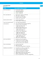
Modular design permits assembly of a large number of
different models and allows substitution of modules if
required. This manual does not cover all possible mod-
els. For more information, see
.
3.3 Function
The function of the FlexFilter is simple. The inlet mod-
ule, level 5 in
, separates coarse particles,
which pass a cone on level 6 and fall down into the col-
lecting module on level 7. Fine dust particles follow
the up-going airflow through the housing on level 3
where the filter unit is installed, level 2.
The particles are separated on the outside surface of
the filter socks. A long spiral spring in each filter sock
keeps it from flattening as air, with a certain pressure
drop, passes through the sock from outside to inside.
Clean air leaves the FlexFilter through the top module,
level 1.
The pressure drop increases as more fine dust settle
on the filter socks. During filter cleaning, part of the
dust is dislodged and falls down into the collecting
module. It is not desirable to dislodge all the dust. A
certain quantity of fine particles on the filter socks
gives much better separation than completely clean
socks.
Different kinds of dust have widely different proper-
ties. Some kinds are easily cleaned off the filter socks
while others require more powerful cleaning. FlexFil-
ter with standard filter cleaning, via a separate control
unit, uses its own vacuum to generate a short blast of
air backwards through the filter socks. A compressed
air cylinder in the top module, opens a disc valve so
that atmospheric air can rush into the FlexFilter to
neutralise the vacuum stored inside. The higher the
vacuum and the larger the connected piping system,
the more air will flush backwards through the filter
socks.
FlexFilter RF (Reverse Flow) has an arrangement of
valves and uses the capacity of the vacuum unit to
clean half the FlexFilter while the other half is in nor-
mal operation. RF is suitable for “hard to clean dust”,
or if the vacuum level is insufficient to generate a
powerful blast of air with standard filter cleaning. The
modular design makes it possible to change the top
module from standard filter cleaning to RF cleaning if
desired.
EN
19
Summary of Contents for FlexFilter
Page 8: ...FlexFilter Figures A B C D 1 A B C D 2 4 3 A B D 5 A B C 6 A B C 7 A B C D F G H A B C F G 1 8...
Page 9: ...FlexFilter A B C D E F 2 9...
Page 10: ...FlexFilter 3 4 5 10...
Page 11: ...FlexFilter 6 7 8 11...
Page 12: ...FlexFilter 9 10 11 12 12...
Page 14: ...FlexFilter Min 2100mm 83 19 B A C 20 21 b a c A B 22 14...
Page 16: ...FlexFilter 25 16...
Page 152: ...www nederman com...


