FlexPAK 800/1000
EN
22
The initial start-up is to be performed with the acoustic enclosure removed to verify the
direction of rotation. Refit the acoustic enclosure when all checks have been performed.
5.2.1
Check the filter cleaning function
When the unit is in Running mode, see Section
‘6.1.3 Running (Running mode)’
, press the
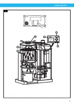
filter cleaning button, see figure 7, item 8, and check that the filter cleaning procedure
starts. The filter cleaning function consists of the Filter Cleaning Valve (FCV), which is a
pneumatic cylinder with a valve disc. The FCV is located at the top of the filter housing
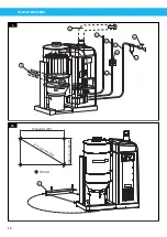
under the enclosure, see figure 8, item 6. A distinct change in sound can be heard as the
valve releases atmospheric air into the filter, indicating that the function works properly.
See also Section
.
5.2.2
Check the automatic start and stop function
NOTE!
This procedure only works if default PLC settings are used.
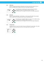
Press the Standby/Running button to put the unit into Standby mode. The unit is not to
start until a valve is opened at a workplace activating its microswitch
,
or the test start/
filter cleaning button is pressed, see the top of figure 8 and Section
. When the valve closes, the unit switches over to Idling mode and after a
delay of approximately 10 seconds, a filter cleaning operation is performed.
After an additional time delay of approximately 12 minutes, the unit will go into Standby
mode.
The filter cleaning delay is set by the DIR_time relay, and the stop delay is set by the SSR_
time relay.
With all valves at the workstations closed, check that the motor slows down (a distinct
change in sound can be heard), and that switching to Idling mode with filter cleaning takes
place after approximately 10 seconds.
Approximately 12 minutes after the unit has switched to Idling mode, it should go to
Standby mode due to the SSR function switching off.
5.3
Start the unit
For more information regarding initial start-up, see the ‘Installation and service manual
’
.
Start the unit as follows:
1.
Turn the maintenance switch to position 1.
2.
Check that compressed air is connected to the unit.
3.
Press the Standby/Running button on the control panel, see Figure 7, item 9. The
white lamp lights up and the display shows ‘Standby’.
4.
The unit starts when the test start button is pressed, Figure 7, item 8, or when a valve
is opened at a workstation.
Always switch off the unit at the end of the shift by pressing the Standby/Running button
on the control panel, or use the weekly timer, see Section
5.4
Unit operation modes
FlexPAK 800/1000 has the following four operation modes:
1.
Off mode
2.
Standby mode
3.
Running mode
4.
Idling mode
Summary of Contents for FlexPAK 1000
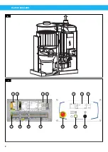
Page 8: ...FlexPAK 800 1000 8 1 2 3 4 5 6 7 14 13 12 11 9 8 10 7 6 ...
Page 10: ...FlexPAK 800 1000 10 9 10 1643 1mm 65 662 1mm 26 2 1771 4 1mm 70 Ø13mm 2 1 4 5 6 8 7 9 3 1 ...
Page 11: ...FlexPAK 800 1000 11 11 12 14 13 ...
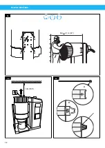
Page 12: ...FlexPAK 800 1000 12 1 0m 39 4 A B C 16 17 15 Min 2 1m 83 A A A A C ...
Page 14: ...FlexPAK 800 1000 14 ...
Page 55: ...FlexPAK 800 1000 55 CS ...
Page 76: ...FlexPAK 800 1000 DA 76 ...
Page 97: ...FlexPAK 800 1000 97 DE ...
Page 98: ...FlexPAK 800 1000 DE 98 ...
Page 119: ...FlexPAK 800 1000 119 ES ...
Page 120: ...FlexPAK 800 1000 ES 120 ...
Page 141: ...FlexPAK 800 1000 141 FI ...
Page 142: ...FlexPAK 800 1000 FI 142 ...
Page 163: ...FlexPAK 800 1000 163 FR ...
Page 164: ...FlexPAK 800 1000 FR 164 ...
Page 205: ...FlexPAK 800 1000 205 IT ...
Page 206: ...FlexPAK 800 1000 IT 206 ...
Page 227: ...FlexPAK 800 1000 227 NL ...
Page 228: ...FlexPAK 800 1000 NL 228 ...
Page 270: ...FlexPAK 800 1000 PL 270 ...
Page 292: ...FlexPAK 800 1000 PT 292 ...
Page 314: ...FlexPAK 800 1000 RU 314 ...
Page 335: ...FlexPAK 800 1000 335 SV ...
Page 336: ...FlexPAK 800 1000 SV 336 ...
Page 356: ...FlexPAK 800 1000 ZH 356 ...
Page 357: ......
Page 358: ...www nederman com ...

