FlexPAK 800/1000
EN
36
5.4
Advance TVFD Valve Settings
5.4.1
Hardware
•
TVFD (SUV) Solenoid Upper Valve (V12)
•
TVFD (SLV) Solenoid Lower Valve (V11)
•
TVFD Upper Position Sensor (UPS) monitoring slide valve (V12)
•
TVFD Lower Position Sensor (LPS) monitoring slide valve (V11)
5.4.2
PLC Settings
1.
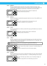
Presep (Softkey) = Off (standard setting)
2.
AEB-TVFD (Softkey) =Off (standard setting=On)
3.
TVFDAdv (Softkey) = On (standard setting= Off)
NOTE!
If TVFDAdv is activated (Switch = On), TVFDAdv overrides 1 and 2 above.
5.4.3
Timer settings
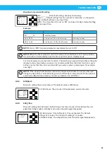
LSOTmr (Bin Emptying Time)
T = Timer sets the Open time (Emptying time) lower slide valve. Default 10 second
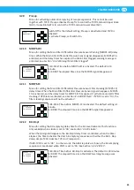
TVFDC-Al
T = sets the maximum time that you can accept it will take to perform the slide valve
closing sequences of upper and lower slide. The default setting is 15 seconds. If the slide
valves do not perform this sequence within the set time, the unit goes into Off mode.
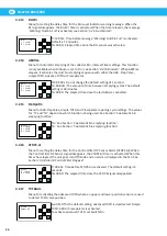
TVFDO-Al
T = sets the maximum time that you can accept it will take to perform the slide valve
opening sequences of upper and lower slide. The default setting is 15 seconds. If the slide
valves do not perform this sequence within the set time, the unit goes into Off mode.
6
Machining chips and swarf extraction
If FlexPAK is used for machining chips and swarf extraction, it is recommend that the unit
be configured for this purpose. See section
‘4.2.25 CoolTmp’
.
When the fan temperature reaches the temperature set in CoolTmp, CoolTmp activates
CoolTmr to open the filter cleaning valve for a set period of time to let air into system to
cool down the fan.
NOTE!
During the cooling cycle, all vacuum is lost in the system so there is no waste
extraction.
When the time set in CoolTmr has elapsed, the filter cleaning valve is closed, and vacuum is
established in the system so waste extraction can start again.
To activate machining, first set the temperature limit parameters in CoolTmp. Set “On=97”
and “Off=96”. Next set the maximum cooling cycle time limit in CoolTmr. Set TH>0. For
example, set “TH=5” for a five second cooling cycle time limit.
See also figure
‘2’
for a description of how machining works.
6.1
Electrical connection of indicator lamp
See figure 22. It is possible to connect an indicator lamp to FlexPAK to show when the
cleaning valve is open so that there is no vacuum in the system.
Connect the indicator lamp to terminal X1:5 (+24V DC) and terminal X1:6 (0V DC). See
figures 21 and 22 to see how to connect the indicator lamp to terminal X1.
Summary of Contents for FlexPAK 800
Page 2: ...FlexPAK 800 1000 2...
Page 3: ...FlexPAK 800 1000 3 Figures 4 English 7...
Page 5: ...FlexPAK 800 1000 5 2...
Page 42: ...FlexPAK 800 1000 EN 42 PLC setting Default value Customer specific value...
Page 43: ......
Page 44: ...www nederman com...


