background image

L-PAK 150/250 Standard

EN

6

Preface

Read this manual carefully before installation, use and service of this product. Replace 

the manual immediately if lost. Nederman reserves the right, without previous notice, to 

modify and improve its products including documentation.
This product is designed to meet the requirements of relevant EC directives. To maintain 

this status, all installation, maintenance and repair is to be done by qualified personnel 

using only Nederman original spare parts and accessories. Contact the nearest authorized 

distributor or Nederman for advice on technical service and obtaining spare parts. If there 

are any damaged or missing parts when the product is delivered, notify the carrier and the 

local Nederman representative immediately.

Safety

This document contains important information that is presented as either a warning, 

caution or note. See the following examples:

WARNING! 

Risk of personal injury.

Warnings indicate a potential hazard to the health and safety of personnel, and how that 

hazard may be avoided. 

CAUTION! 

Risk of equipment damage. 

Cautions indicate a potential hazard to the product but not to personnel, and how that 

hazard may be avoided.

NOTE! 

Notes contain other information that is important for personnel.

Description

WARNING! 

Risk of personal injury.

See the User manual.

Unit operation

4.1 

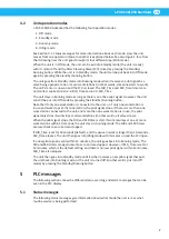
Software with extended functionality

L-PAK 150/250 Advanced comes with extended software and standard Logo! PLC display 

that allows a technician to easily set parameters and read status messages.

NOTE! 

If the software is used in a logo without a display, it is not possible to change 

parameter settings.

Summary of Contents for L-PAK Series

Page 1: ...L PAK Series L PAK 150 250 Standard 50Hz 60Hz 2130224 00 2018 09 13 Original PLC manual EN PLC MANUAL PLC Manual...

Page 2: ......

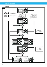
Page 3: ...L PAK 150 250 Standard 3 Figures 4 English 5...

Page 4: ...m ESC OK Hi Vacuum Unit Running Time 05 33 Min DIRTm 00 00 s OTTmr 00 00 h ESC OK Hi Vacuum Unit IDLING Time To StandBy T 05 33m PS PS ESC OK Hi Vacuum Unit Running Time 05 33 Min DIRTm 10 00 s OTTmr...

Page 5: ...1 5 Filter Cleaning 9 5 1 6 Status report 9 5 2 Warning messages 9 5 2 1 Time for service 10 5 2 2 Warning Fan Hi Temp 10 5 3 Alarm messages 10 5 3 1 Alarm Fan Hi Temp 11 5 3 2 Alarm Motor Protector...

Page 6: ...ocal Nederman representative immediately 2 Safety This document contains important information that is presented as either a warning caution or note See the following examples WARNING Risk of personal...

Page 7: ...f only one work station is in use and work stops at that one station the pilot signal stops If there is more than one work station connected to the unit and more than one work station is in use the pi...

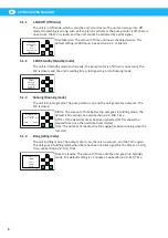
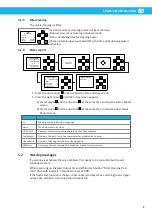
Page 8: ...r Pilot Signal Mo 15 33 2018 01 22 5 1 3 Running Running mode The unit in Running mode The pump motor is on and the unit generates a vacuum The FCV is closed ESC OK Hi Vacuum Unit Running Time 05 33 M...

Page 9: ...en appears 1 Press Escape ESC and the up arrow at the same time to show the Status Report screen 2 Press Escape ESC and the up arrow at the same time to show the next Status Report screen Sn Software...

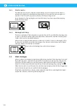
Page 10: ...vates a timer start which is shown in the display if the fan does not cool down when the timer elapses the vacuum unit will stop and the Alarm message Alarm Fan Hi Temp is activated ESC OK Warning Fan...

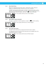
Page 11: ...Alarm Fan Hi Temp Vacuum Unit O Th 11 23 Reset OK Th The actual day and time when L Pak was stopped 5 3 2 Alarm Motor Protector Activated The motor is overheated Correct the problem and press OK OK to...

Page 12: ...3 Press the down arrow to go to Program Press OK OK to confirm 4 Select Set Parameter Press OK OK to confirm 5 Use the up or down arrows to find the parameter Press OK OK to confirm 6 Use the left and...

Page 13: ...confirm 5 Press the down arrow to go to Set Clock Press OK OK to confirm 6 Use the left and right arrows to move to cursor to parameter value Press OK OK to confirm 7 Use the up or down arrows to set...

Page 14: ...filter cleaning ESC OK FCTmr 1 1 Stat ON TH 01 00s TL 60 00m Stat On Filter Cleaning timer activated Default is On TH 01 00s Do not change the default setting of 1 second TL 60 00m Time between automa...

Page 15: ...4 Warning Alarm output Q4 Potential free output Terminal X1 33 34 When an alarm is activated Output Q4 and White lamp button on the control box side flash with interval 1 second on 1 second off Warnin...

Page 16: ......

Page 17: ...www nederman com...

Reviews: