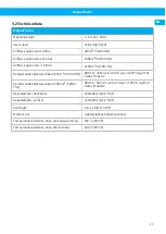
MagnaTrack S
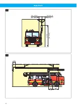
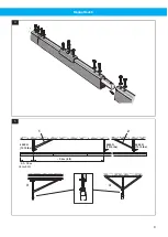
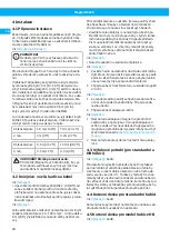
4.5 Anchor plate for nozzle model HB
See
The anchor plate should be fitted to the side of the
vehicle 600 mm (23.6 in) or 900 mm (35.4 in) from
the exhaust pipe. If necessary this distance can be
changed (+100 mm, -25 mm / +4 in, -1 in) by loosen-
ing the adjusting screw in the electromagnetic unit.
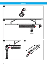
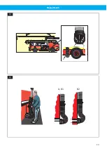
4.6 Standard nozzle
See
1
Fit the chain lock in the electromagnetic unit as
shown in the figure. Fit the hose in the electro-
magnetic unit with the hose clip and cover with
the rubber ring. Check that the nozzle, when not
connected to the vehicle, is pointing forward in
the driving direction.
2
To adjust the spring power in the nozzle after fit-
ting the anchor plate, use the adjusting screw
marked 1.
3
If necessary, adjust the elastic cord length so that
the nozzle comes in the required position and
fasten the quick- coupling in the electromagnetic
unit.
See
and
item A.
1
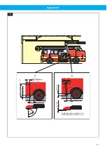
In the opening of the standard nozzle there are
two landing (friction) pads, one made of steel (2),
the other of rubber (1). The steel pad (2) must be
the most front one when viewed in relation to the
forward drive direction of the vehicle.
2
Locate the nozzle on to the exhaust pipe and se-
cure the electromagnetic unit on the anchor plate
making sure the hose is tensioned correctly. The
hose should form a 90° bend coming out from the
exhaust pipe.
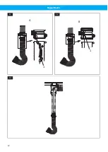
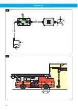
4.7 Nozzle model HB
See
and
.
1
Fit the nozzle leaf spring in the electromagnet-
ic unit with the adjusting screw as shown in the
figure. Fit the hose in the magnetic unit with
the hose clip and cover with the rubber ring.
Check that the nozzle, when not connected to the
vehicle, is pointing forward in the driving direc-
tion.
2
To adjust the nozzle after fitting the anchor plate,
use the adjusting screw marked 1 to move the leaf
spring some upwards or downwards.
3
If necessary, adjust the elastic cord length so that
the nozzle comes in the required position and
fasten the quick- coupling in the electromagnetic
unit.
NOTE!
If the leaf spring is moved upwards it must not
come in contact with the upper hose. If nec-
cessary its upper end should be cut off.
item B1 or B2.
• Locate the nozzle on to the exhaust pipe and secure
the electromagnetic unit on the anchor plate mak-
ing sure the hose is tensioned correctly. The hose
should form a 90° bend coming out from the ex-
haust pipe.
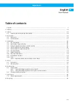
4.8 Electrical installation
See wiring diagram in
mains is to be carried out by a qualified electrician.
1
Transformer (not included in the package). Se-
condary voltage: 24V AC. Protection class IP54.
Power: 5VA.
2
Service breaker (not incl. in the package)
3
Power supply
4
H05RN-F 3G 1,5 mm
2
(USA: SJ 3 x AWG 15)
5
Horizontal hose with cable
6
Disconnection box
7
Disconnection magnet
8
24 V DC
9
Vertical hose with cable
10 Circuit breaker
11 Electromagnet
12 VDR
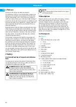
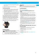
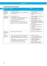
4.9 Installation checklist
When the mechanical assembly, fan connection and
electrical installation of MagnaTrack S is complete, the
system is ready for use after double-checking the fol-
lowing points:
1
Check the disconnection procedure. The extrac-
tion hose should disconnect from the exhaust pipe
immediately before the station door opening at
normal speed, not more than 15 km/h (10 mph).
Adjust the disconnection position by moving the
disconnection magnet on the front rail, see
.
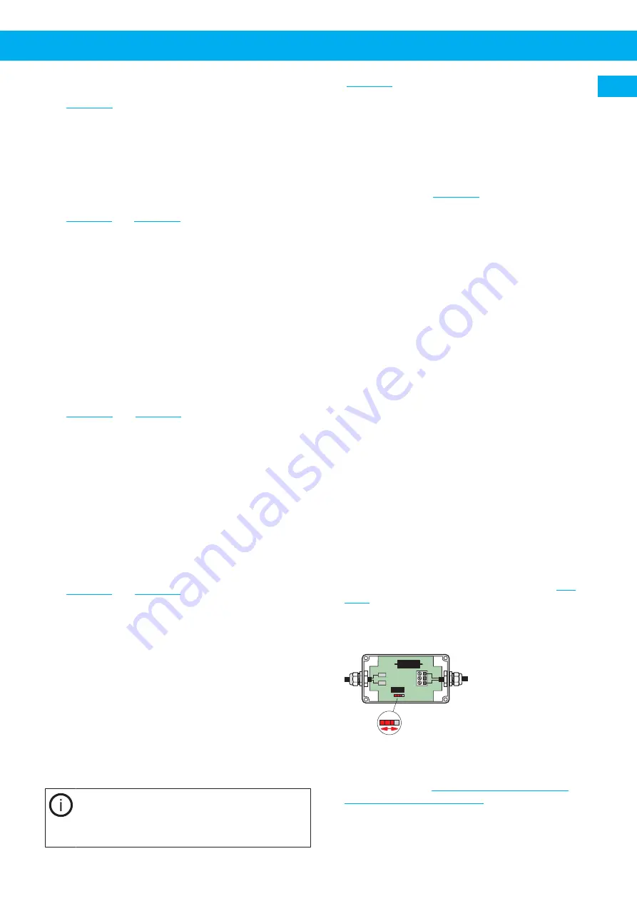
2
If the disconnection does not work at all in the for-
ward direction, move the contact in the disconnec-
tion box according to this figure.
3
Check that the hose lifts away correctly after dis-
connection and that it does not touch the station
floor. When required, adjust the cord length in the
vertical hose, see
.
4
Check that the hose and the nozzle do not catch
any part of the vehicle or the station door.
EN
19
Summary of Contents for MagnaTrack S
Page 8: ...MagnaTrack S 0 3 0 5 m min 0 3 m 3 5 m 12 20 in 12 in 10 16 ft 2 1 0 m 3 ft A 0 3 m 12 in 3 8...
Page 10: ...MagnaTrack S M8 x 12 6 7 8 m min 0 8 m in 2 5 ft 9 10...
Page 12: ...MagnaTrack S 1 A 11 1 B 12 13 12...
Page 13: ...MagnaTrack S 1 2 2 14 A B1 B2 15 13...
Page 14: ...MagnaTrack S PE 2 3 4 5 6 7 8 9 10 12 11 1 16 max 1 m max 3 ft 17 14...
Page 95: ...www nederman com...


